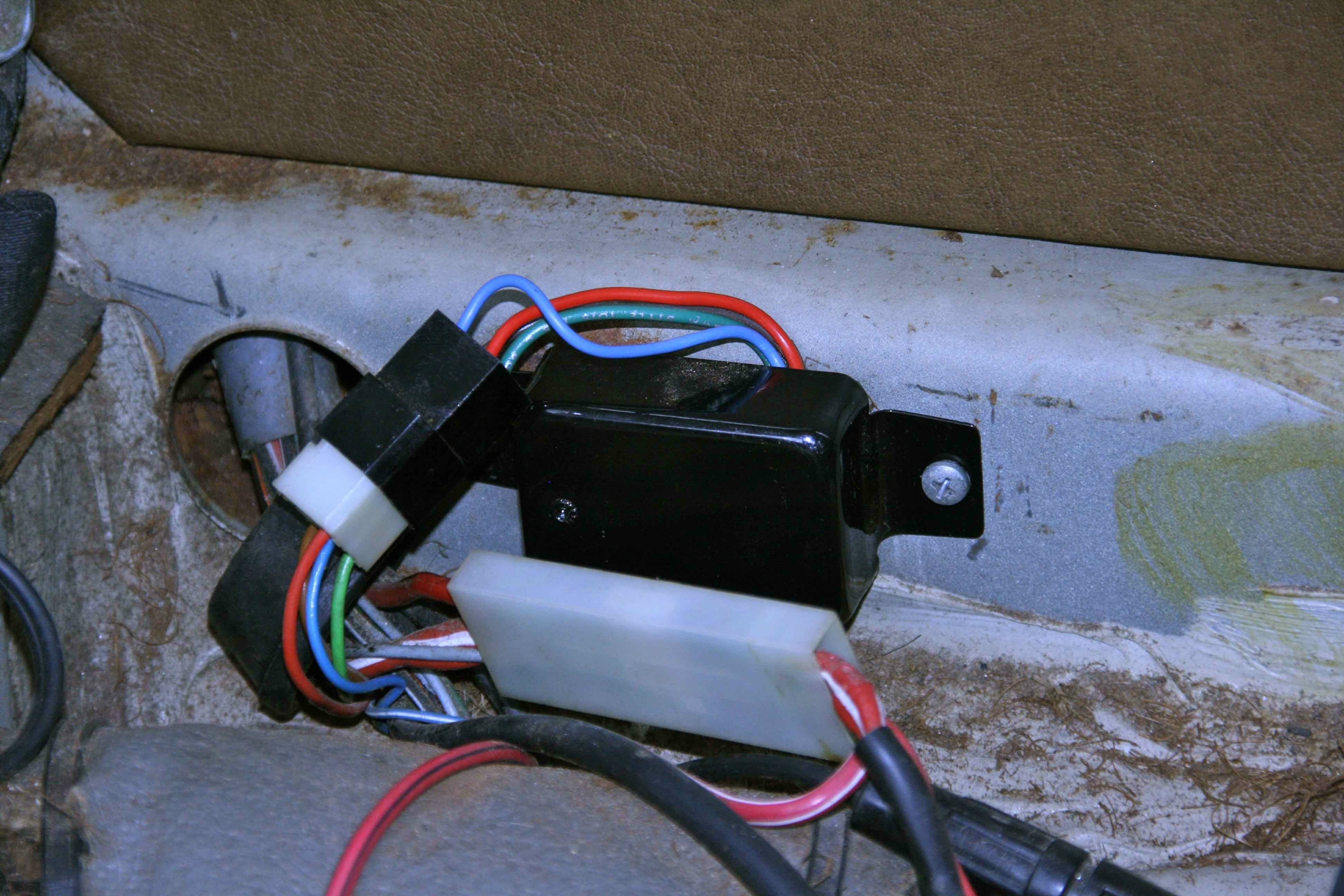
I want to wire a Sterling Alternator to Battery (AB) charger to it. I have to take a wire from B+ and “remove the battery voltage sense wire” if it has one.. what would that Essential IMO to refer to the engine wiring diagram.
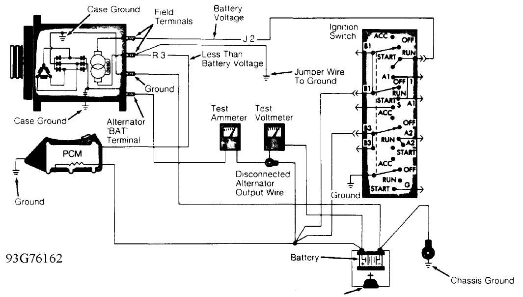
Section A: Wiring Diagram. charging system; the greater the battery discharge level, the lower the system voltage at battery positive terminal or alternator B+. need to be added from alternator ground to battery ground. A jumper wire is supplied to connect the alternator (S) terminal to the (B+) terminal.

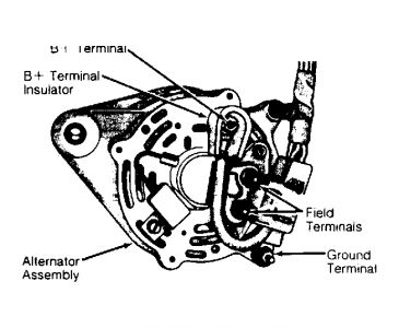
When fitting like for like there’s no issue, but somnetimes you need to wire something up, or adapt a unit to fit an application so Alternator Terminals Explained B+, BATTERY, Main Battery Feed This chart is available for download here. The electrical connections to the F, G and K-type alternators are shown in the diagram. If the sense wire is connected to the alternator B+ terminal, the battery .Nov 16, · I have a 24v CAV alternator (AC5 or AC7 I think) for various reasons I disconnected it and can’t find my notes to reconnect the alternator to the regulator.
It looks fairly simple, there are two large black cables from the alternator, marked “B-” & “B+” which I presume go to the battery and two smaller red cables which need to connect to terminal “A” and terminal “F” on the regulator. 6.
Connect the output cable (see cable sizing recommendations below) ground, field wire, stator (tach) wire if needed and other necessary wiring. Connect alternator to Balmar regulator wiring harness as indicated in wiring diagram included on Page The alternator’s positive and ground cables should be sized according to the chart on Page 3.

– Cadillac CTS Fuses. Battery Alternator Fuse Box Diagram – Fuse For Alternator – Basic Electronics moreover Wiring Diagram 92 Chevy Truck 4×4 as well Simplicity Starter Generator Wiring Diagram also 99 Ford Taurus Wiring Diagram in addition Battery Relocation Clarification Needed. furthermore cat brain diagram also ford ranger fuse box diagram also toyota charging.
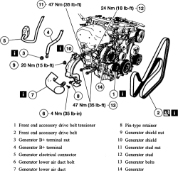
Section A: Wiring Diagram CEN C Alternator Description and Operation C 14 V ( A) alternators are self-rectifying. All Connect B+ battery cable to alternator.
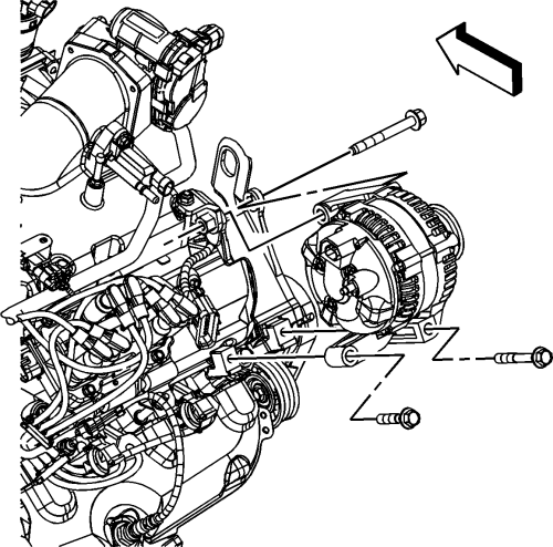
Turn on battery switch. Install a jumper from pin F in harness plug to B+ terminal on alternator. Momentarily (1 sec.) jumper pin A in harness plug to.
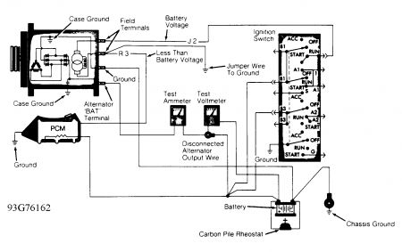
battery (+) terminal on the alternator to lower the output voltage for 34SI, 35SI & 36SI alternators. If necessary, use an 18 AWG minimum wire size terminated with ring terminals to fit remote sense and battery (B+).
Securely crimp and solder the connections. TYPICAL WIRING DIAGRAM LOWER OUTPUT VOLTAGE: VOLTAGE CAN BE REDUCED BY INSTALLING A JUMPER.B+ (Alternator) to Battery cable (size)Wiring an alternator – Boat Building & Maintenance – Canal World
