Turf/Carryall Vehicle Maintenance and Service Manual.
Publication Part No . .
Engine Ignition Circuit. . Accelerator Pedal Limit Switch.
This manual covers all Club Car® DS Tranquility®, DS V-Glide Volt, DS PowerDrive® System. 48™ and DS ..
FE ENGINE— CRANKCASE, CAMSHAFT AND OIL SENSOR. . WIRING—POWERDRIVE SYSTEM 48 VEHICLE.
. WHITE POT LIMIT SWITCH LEAD, CONNECT BLUE LEAD TO BATTERY.
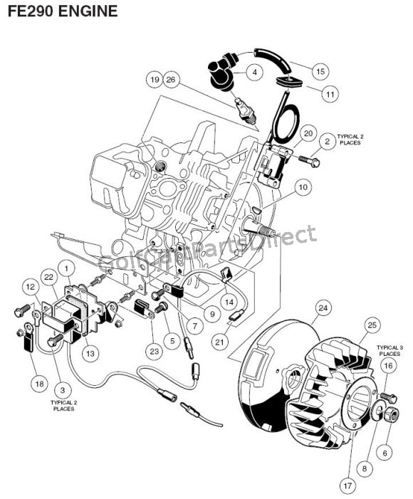
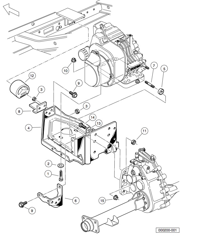
USING THE ILLUSTRATED PARTS LIST. This manual is to be used for identification and ordering of service parts for the DS Gasoline and DS .
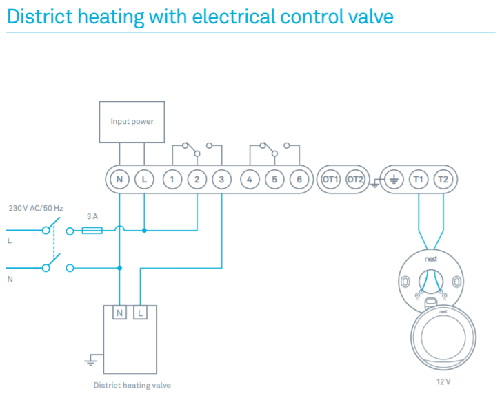
ELECTRICAL AND BAITERY. SECTION 5.
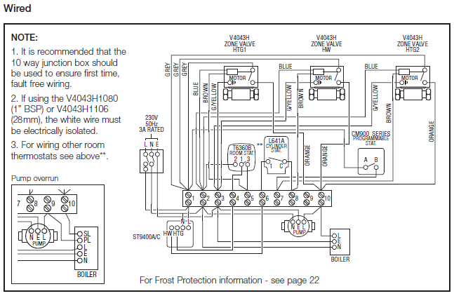
Wiring. Gas Vehicle.
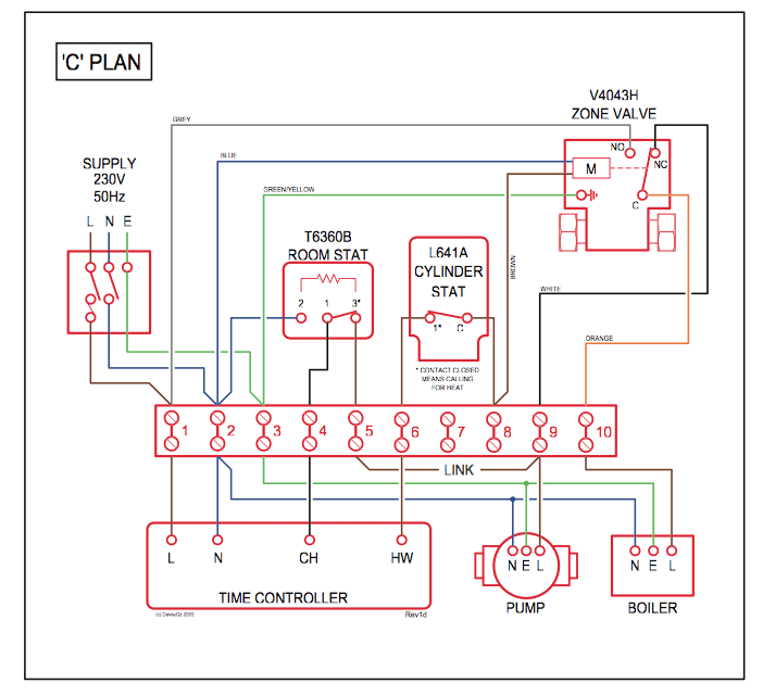
FE OHV GASOLINE ENGINE – COMPLETE. BOLT FORWARD AND REVERSE LIMIT SWITCH. 1.

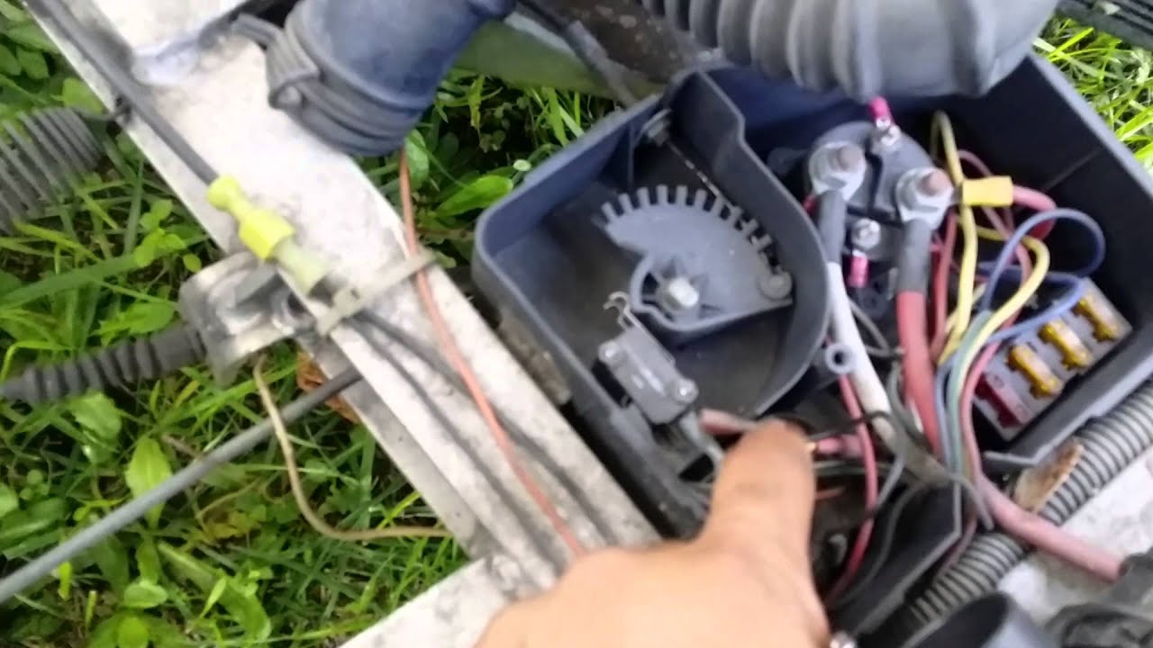
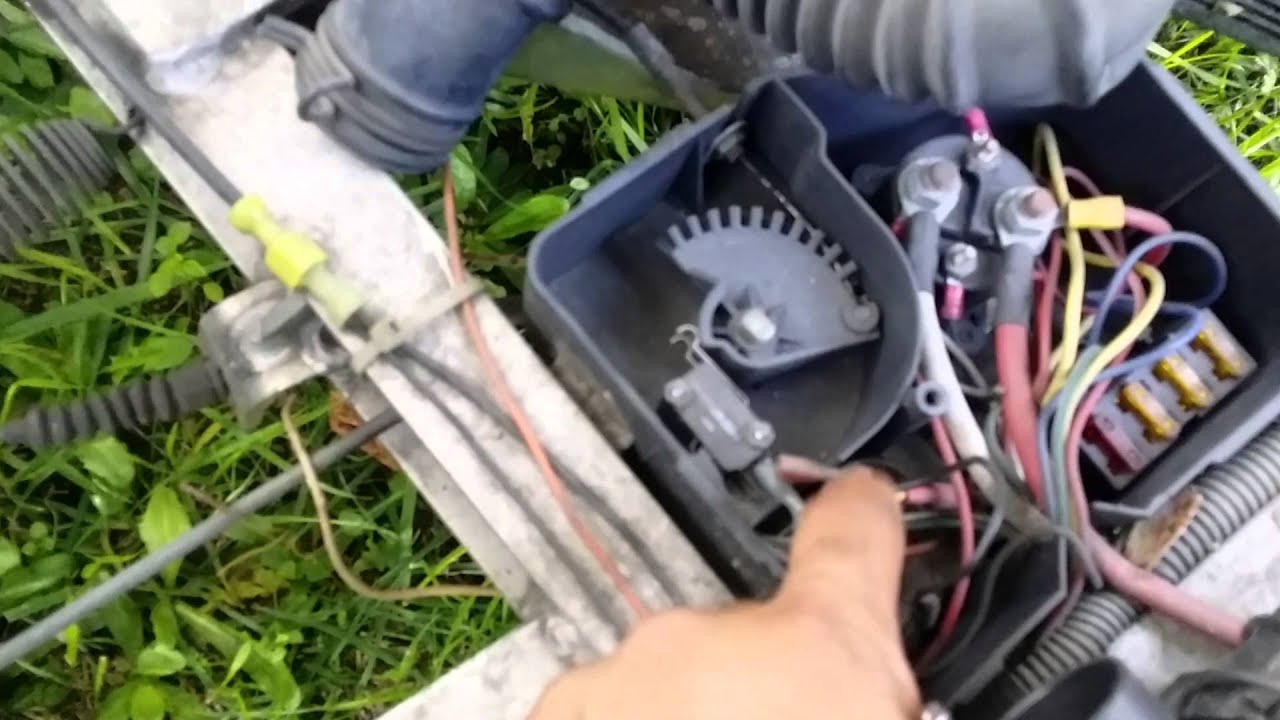
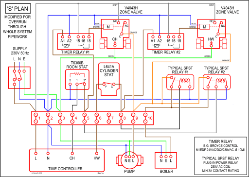
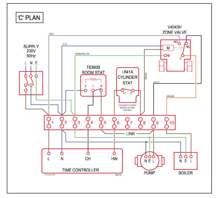
Club Car FE Manual Online: Engine Kill Circuit, Reverse Buzzer Circuit. The engine kill circuit consists of the key switch, a kill limit switch that is activated . Do not see that in the electrical diagram. When I unplug the wires from the top micro switch it does not start so that must be the starter micro switch.
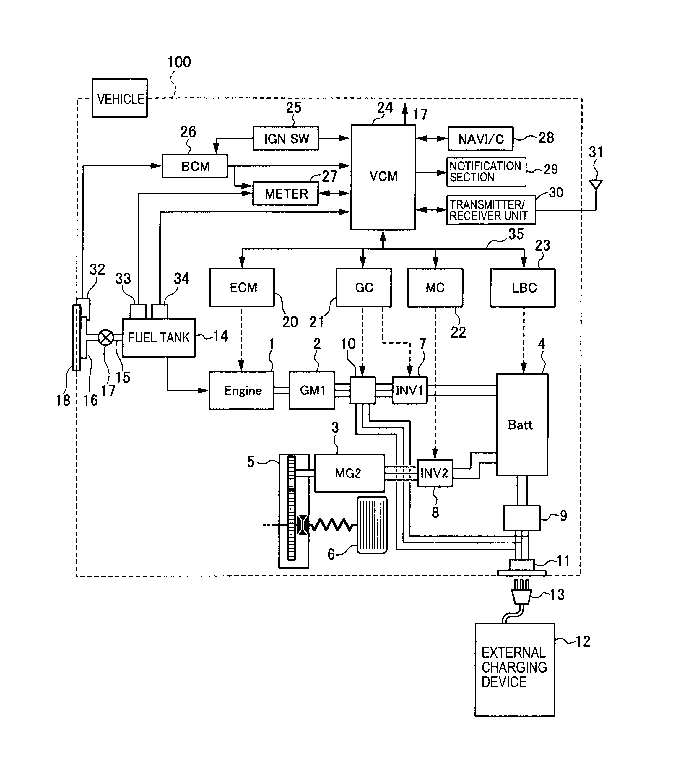
I then I have an FE in a Kawasaki Mule, in my shop today, that does not use igniter!.jumpers/splices are required to connect the Golf/Street Switch, and optional Brake light Relay. Connect the Yellow wire to the + (positive) side of the reverse buzzer, and the Gray wire to the – (negative) side. See DIAGRAM Connect a Blue wire from the key switch to terminal 2 on the Golf/Street switch, and the Brown wire to terminal 1.
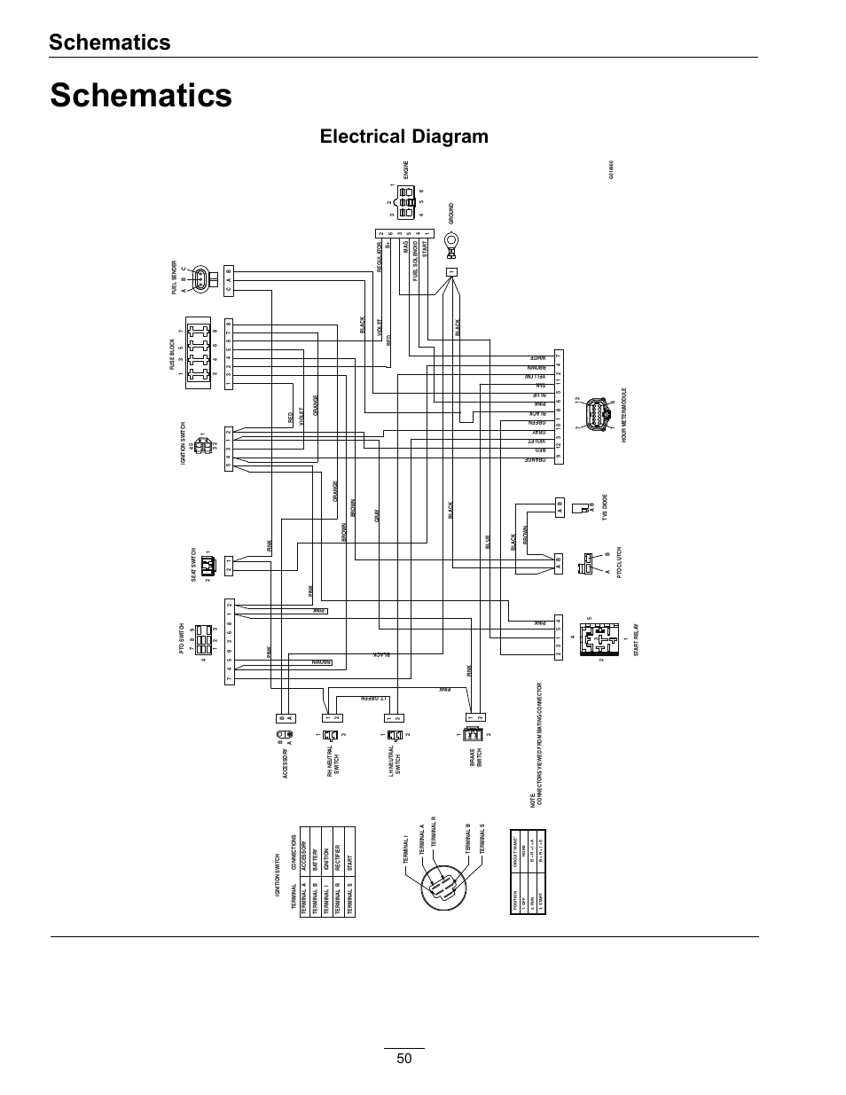
Installation Instructions for the ISSUE 4 MICRO SWITCH™ Heavy Duty Limit Switch Series PK wiring and conduit connection is made to the base receptacle. This feature also reduces MICRO SWITCH™ HDLS Mounting Diagram.
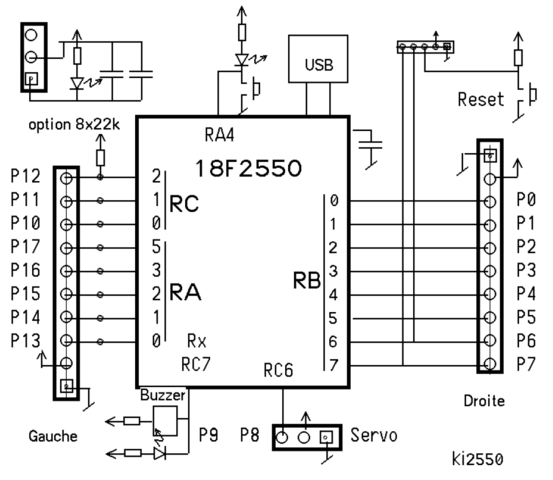
MICRO SWITCH™ HDLS Series ISSUE 4 PK Sep 03, · I used Photoshop to just trace over the original wiring diagram and add the colors. Can you post your key-start diagram? I imagine most of it will be similar to the diagrams I’ve already done, with just a few wires re-arranged in the starter circuit?
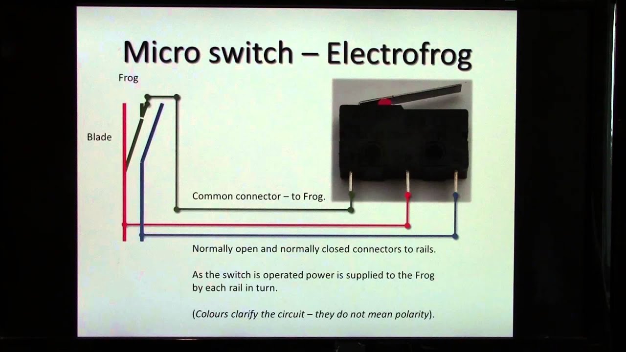
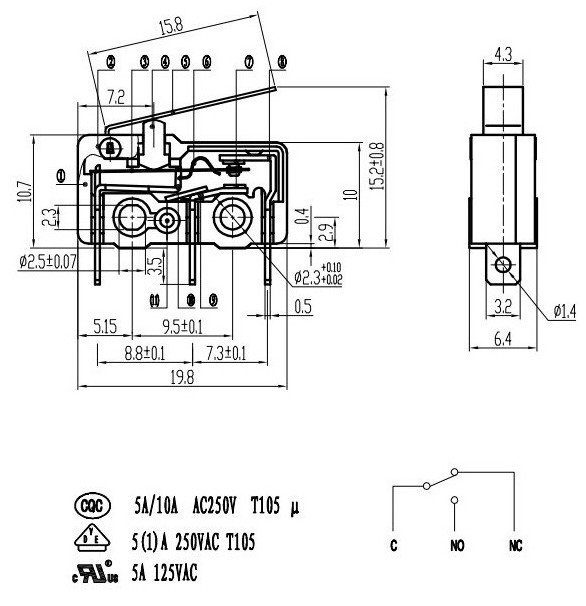
SWITCH DAMAGE • Wiring must be rated to meet or exceed circuitry MICRO SWITCH™ V-Basic Standard V15 ISSUE 3 CIRCUIT INFORMATION A circuit diagram is included on the switch case labeling each of the terminals. The normal position corresponds to the switch .
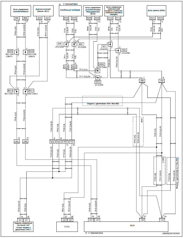
Find great deals on eBay for club car micro switch. Shop with confidence.Gas Golf Cart Club Car Rpm Limiter Wiring Diagram | Wiring LibraryHow to change the Micro Switch on a Club Car Gas Golf Cart Video
