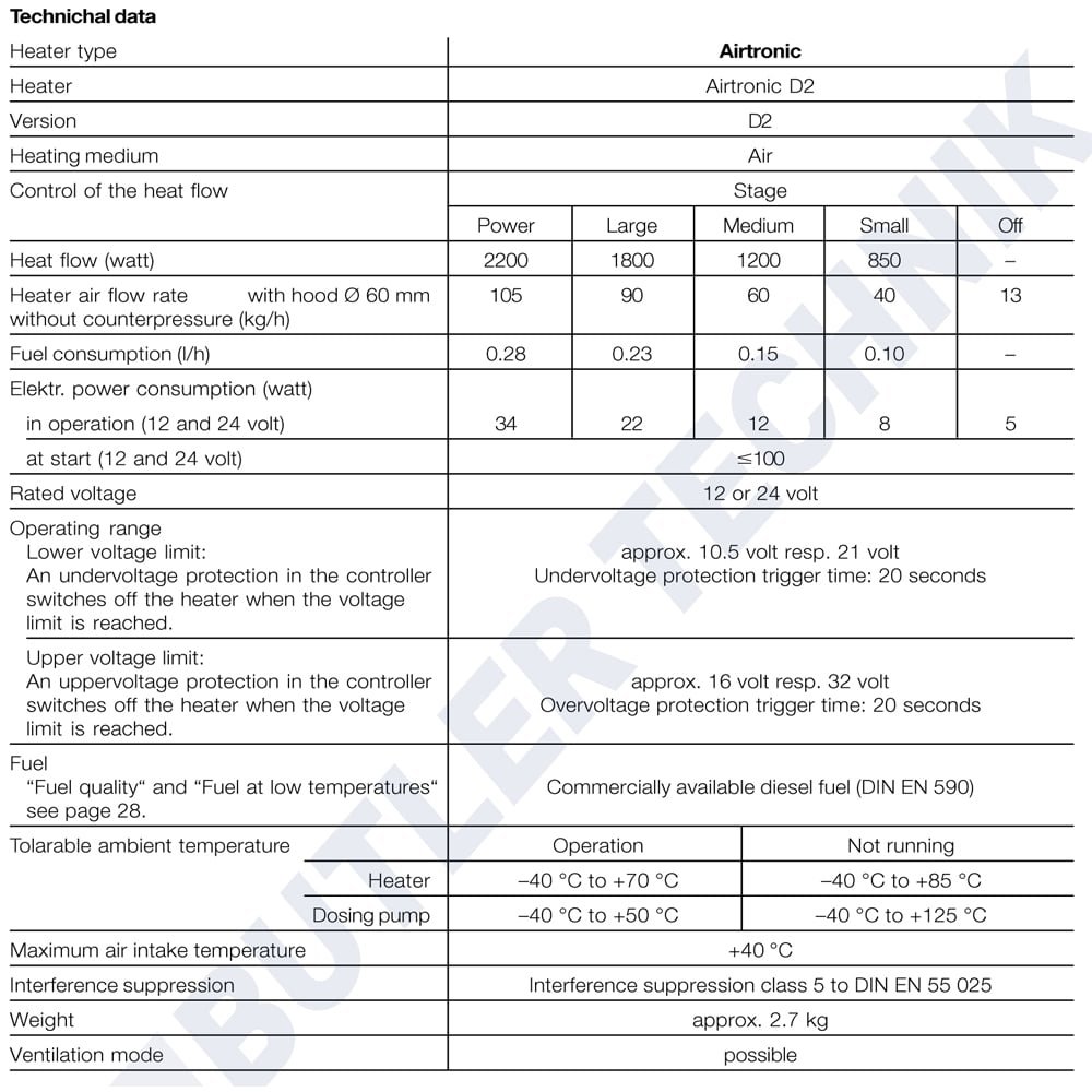
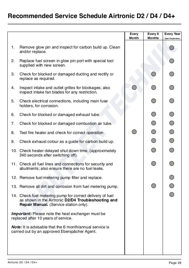
Troubleshooting and Repair Instructions. 25 95 19 Airtronic.
Order no. Airtronic D2, 12 V. 25 05 00 Airtronic D2, 24 V.
25 05 00 . Troubleshooting and Repair Instructions. 25 95 19 Airtronic.
Order no. Airtronic D2, 12 V.
25 05 00 Airtronic D2, 24 V. 25 05 00 .
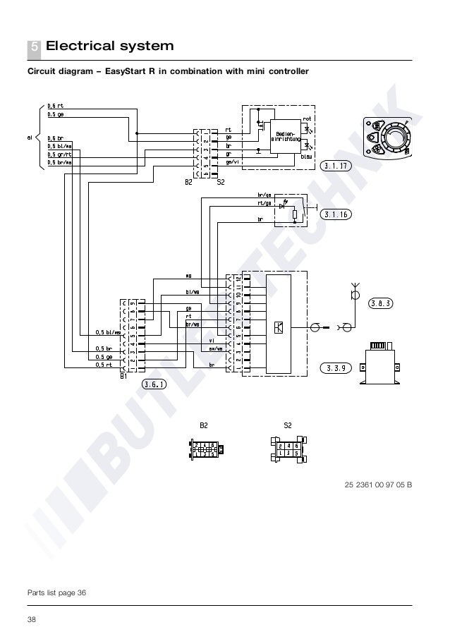
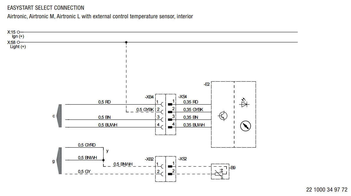
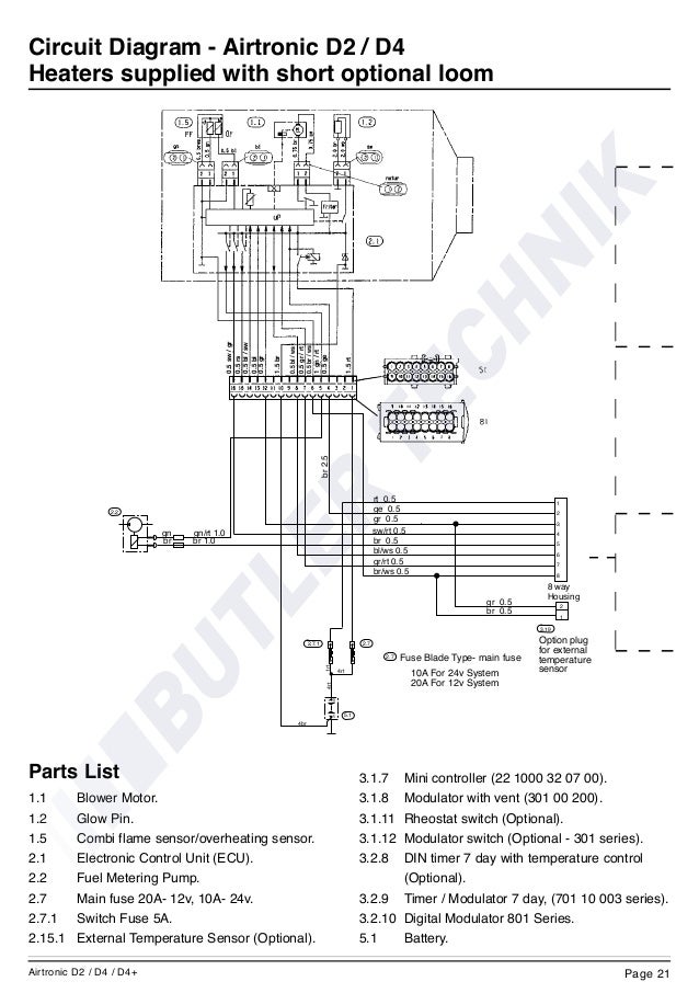
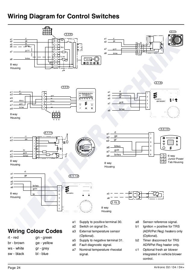
Eberspächer Airtronic D2 Manual Online: Wiring Diagram For Control Switches. rt 1 ge 2 br 5 bl/ws 6 gr/rt 7 br/ws 8 8 way Housing rt 1 ge 2 5 bl/ws 6 gr/rt 7 br/ws.
How to fit an Eberspacher night heater to your VW Campervan. In this blog post we’ll lay out how to install the Airtronic D2. Airtronic installation manual (on CD / Eberspaecher website); EasyStart user manual (on CD .
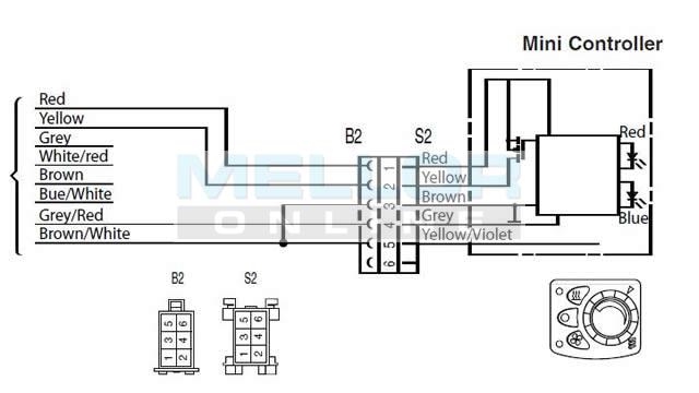
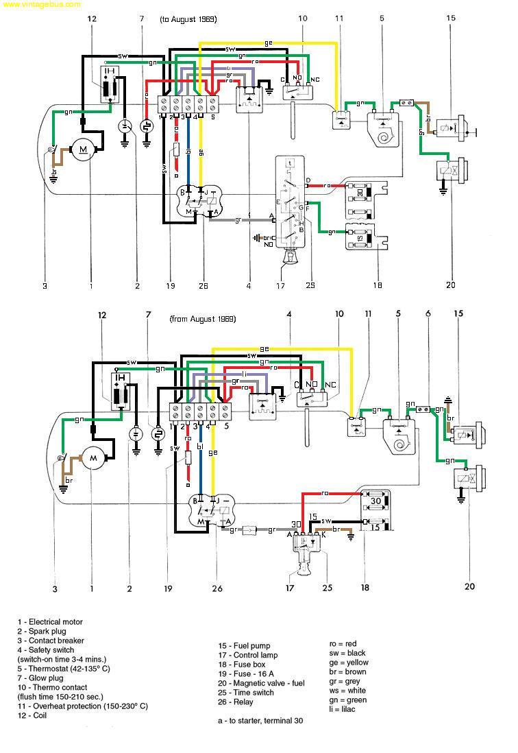
If you have a different one, check the wiring diagram for your model.Eberspacher wiring modern air heaters Airtronic D2 D4 D5, D1LCC D3LCC, D1LC D3LC D5LC The installation manuals cover many of the details and I recommend downloading and studying the manual before starting, see Manuals page. Technical wiring diagrams are not my strong suit. My Espar works great.
I’m satisfied that it’s a clean, professional installation. My DIY post may contain errors. Espar Heater Installation- DIY Guide By RadVan Adventures • February 12, Espar Airtronic D2.
duplicate any technical information here. Espar (Eberspacher), is a large. Eberspacher D2 Diesel Heater – kW Motorhome Kit – Shop RV World NZ Eberspacher Airtronic heater diagram Servo Controller Wiring Diagram – Opinions About Wiring Diagram • servo controller solder spot rh solderspot wordpress com Airtronics Servo Reverse Direction RC Airplane Servo Wire Diagram.
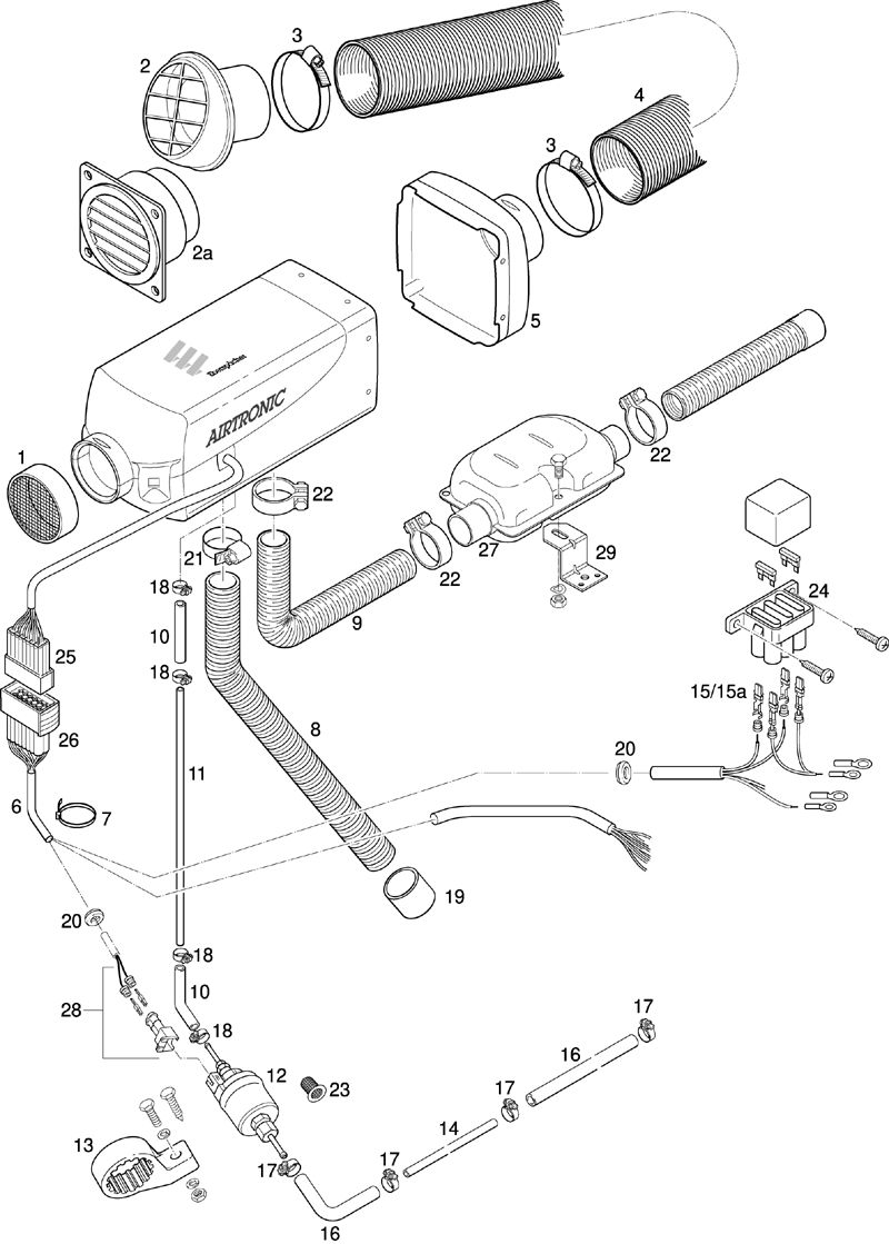
AIRTRONIC / AIRTRONIC M Technical description, installation, operation and maintenance instructions. Air heater for diesel and petrol operating independently of the engine. Airtronic Order no.
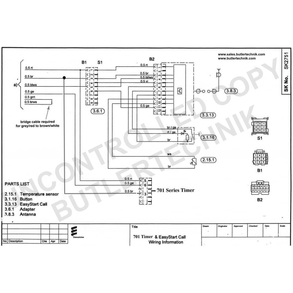
Airtronic D2, 12 V 25 05 00 00 Airtronic D2, 24 V 25 05 00 00 Complete package Airtronic D2, 12 V 25 05 00 00 Airtronic D2, 24 V 25 Function diagram AIRTRONIC D2 Function diagram AIRTRONIC D4 Page Schematic Airtronic D2 / Airtronic D4 Schematic AIRTRONIC D2 / AIRTRONIC D4 Wire color key Designation for switches red = power (+) yellow = switch brown = ground (-) grey = temperature sensor on thermostat vehicle dimmer switch for light display on 7-day timer grey/red.Wiring diagram Eberspacher Airtronic [Archive] – Yachting and Boating World ForumsESPAR AIRTRONIC D2 INSTALLATION INSTRUCTIONS MANUAL Pdf Download.