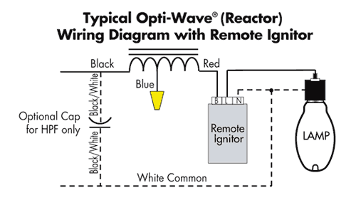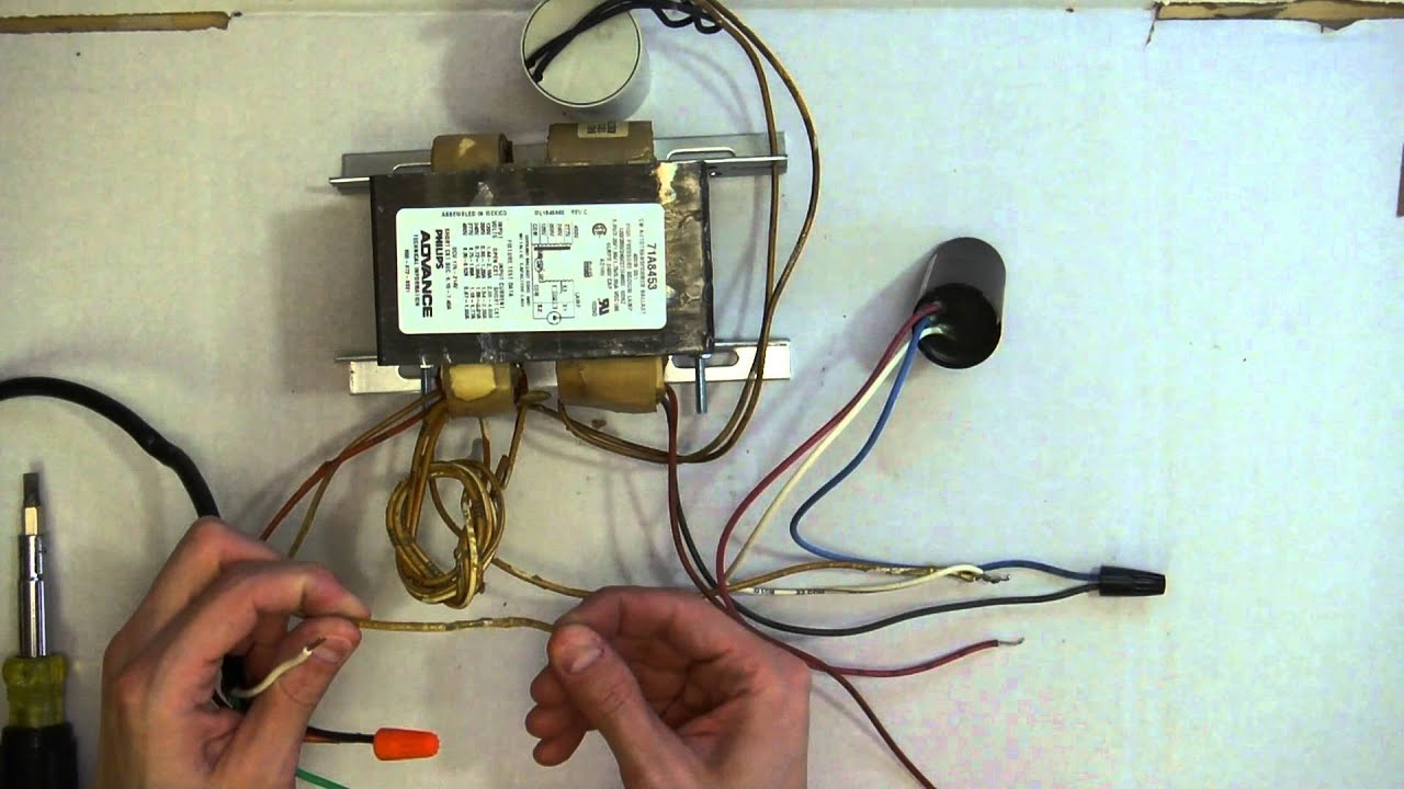
Refer to wiring diagram on ballast label for proper component connections c) Wire product in accordance with local and national electric codes .

(also, for HI High Pressure Sodium CWA type ballasts with model number. Refer to wiring diagram on ballast label for proper component connections c) Wire product in accordance with local and national electric codes .
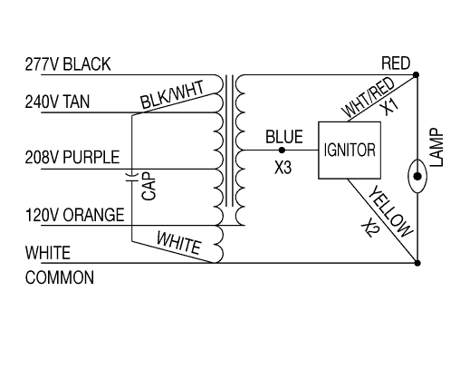
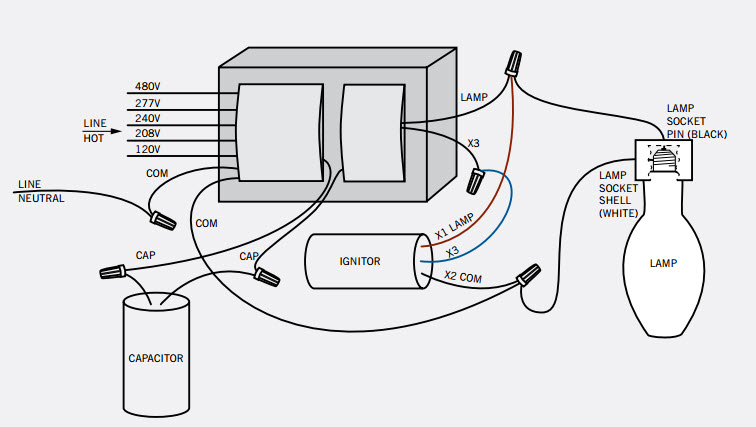
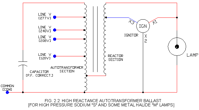
(also, for HI High Pressure Sodium CWA type ballasts with model number. Wiring diagrams for Venture® HPS and remote ballast products are provided on this shock hazard, personal injury or damage to the luminaire or installation. High-pressure sodium ballast lamps use high pressures of sodium, in an excited state, to generate light.
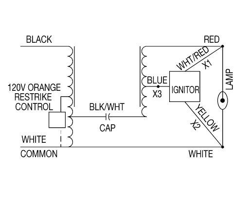
Locate the wires labeled “com” and “” on the short side of the transformer Venture Lighting: Additional Ballast Lighting Diagrams. High Pressure Sodium Ballast Wiring Diagram . Metal Halide Ballast Wiring Diagram (Pulse Start) How to you wire V input Do I hook 1 hot.Here’s a larger view of the wiring diagram.
Notice how both the red and blue wires go to one lamp. The yellow wires are, for lack of a better description, are “shared” so pin 1 of lamp 1 and pin 1 of lamp 2 go one yellow wire.
Afterwards, connect the bare wire to the base of the transformer or to the enclosure. Install the enclosure to cover the ballast and tighten the screws.
Step 5 – Testing. Check to make sure that all connections are correct and complete.
Install a bulb onto the socket and plug the ballast to a power supply. If the light works, the wiring is successful.

Locate the wires labeled “com” and “” on the short side of the transformer and connect the “com” wire to the white wire on the power cord and the “” wire to the black wire on the power cord. Install the enclosure, per manufacturer’s instructions, to cover the ballast.
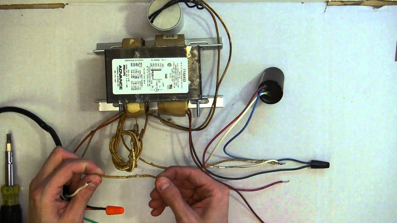
Sep 10, · Although, most stores were pushing their own ballast that was essentially a Quantum made at the same manufacturing plant with a different fan and a different name on the product. My original idea was to try to find a W Ballast that supports W and W Bulbs and start at W in a smaller space and eventually move up.
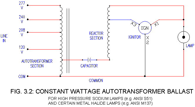
The wiring diagram is the blueprint for the ballast circuitry, including the input supply voltage and grounding methods. A ground connection must be made to all ballasts to avoid shock hazard, personal injury or damage to the luminaire or installation.Additional Ballast Wiring Diagrams – HPS ballastsAdditional Ballast Wiring Diagrams – HPS ballasts
