
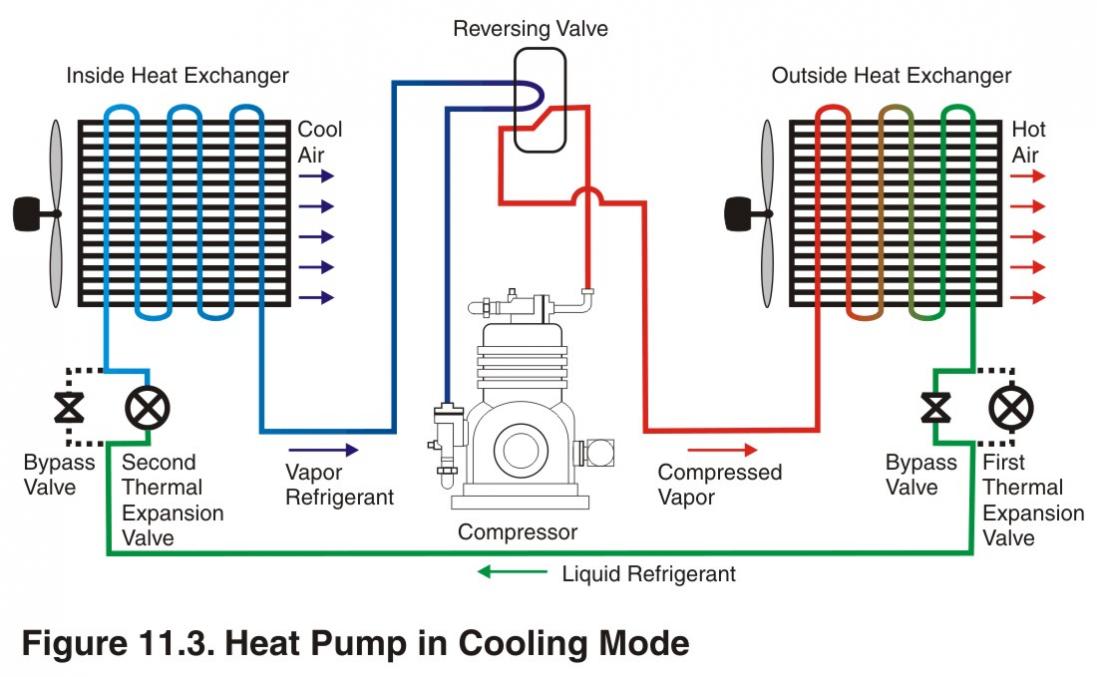
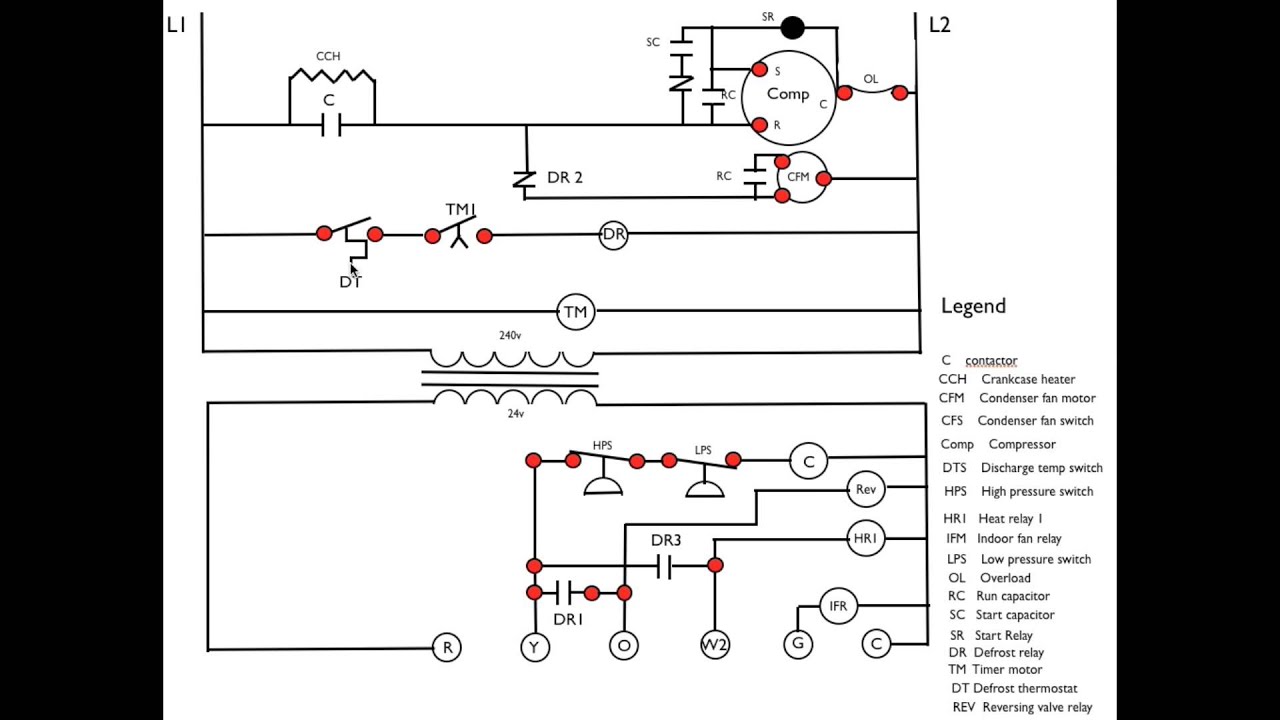
Daikin RoofPak applied rooftop unit, models RPS, RDT, RFS and RCS. On units that include gas heat, the nameplate is located on the lower right corner on the See Control Panel on page 8 for the Wiring Diagrams on page Use a vacuum pump with a pumping These sequences describe the ladder wiring .
Daikin Altherma, Split, Sky Air and VRV ranges. › BES .
VRV IV heat pumps for indoor installation. You can No need to use a ladder to reach the unit.
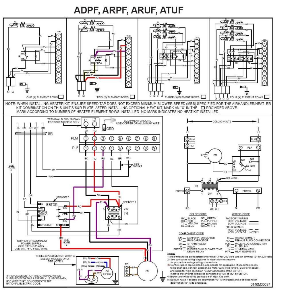
Using the proper mini split communication wire is critical to a properly The installation manual for your unit will specify the weight of LG and Daikin are the leaders when it comes to reliable, long . Should we call another HVAC guy, get a new unit or just keep the ladder out and bang on it periodically?. Thermostat Wiring Diagrams – Heat pumps are wired for HVAC control far shows a slightly different type of wiring diagram that mirrors a ladder logic diagram.
Service. Manual. Inverter Pair.
FTXS-L Series. FDXS-L Series. SiUS [ Applied Models].
○ Inverter Pair: Cooling Only. ○ Inverter Pair: Heat Pump.connection diagram o bl o bl ladder diagram ps2 ps1 t1 t3 lp/hp fan y-rv rv rv coil cc c defrost control ps2 coil ps1 df rywc o r-rv lp/hp lp/hp sen two switch wiring fm cap defrost heat compressor heat/cool 24 vac lar 1 las low ambient relay defrost r y bl bl bl g sec trans pri r bl bl r reset 24v transformer note 4 /v bk t1 l1 cont. Download Daikin Heat Pump PDF manuals.
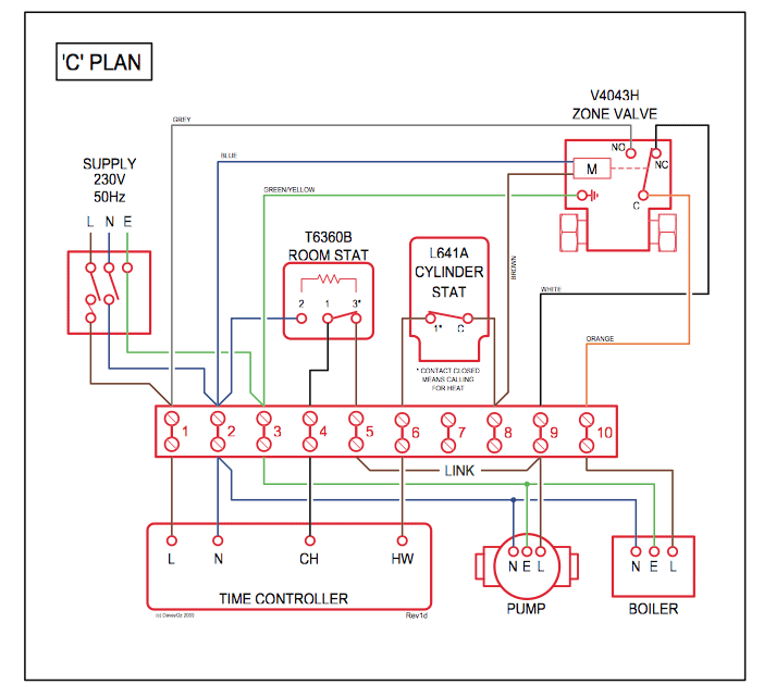
User manuals, Daikin Heat pump Operating guides and Service manuals. Thermostat Wiring Diagrams – Heat pumps are wired for HVAC control far differently than air conditioning systems so make sure you know the difference and correctly identify the type of HVAC system you have installed.
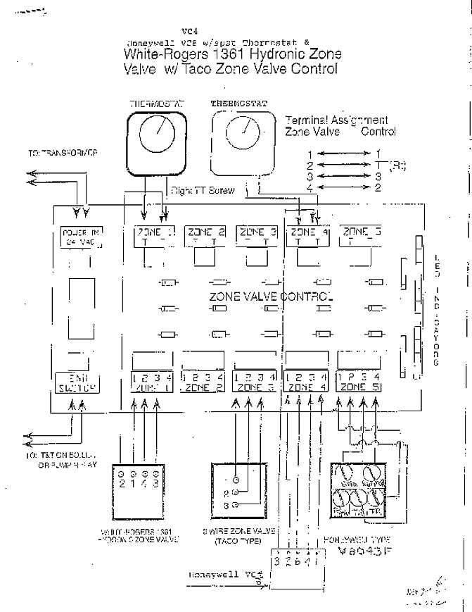
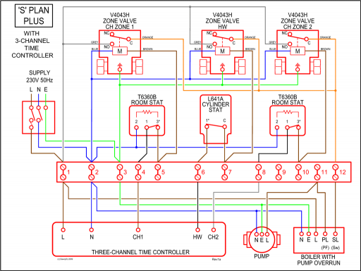
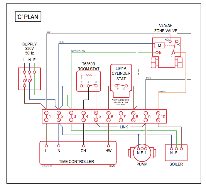
Thermostat Wiring Diagrams. before installing an air conditioner or heat pump. After completing the installation, make sure that the unit operates properly during the startup operation.
Instruct the user on how to operate and maintain the unit. Inform users that they should store this installation manual with the operation manual for future reference.
Oct 11, · Learning tech, Here are a couple of pictures of wiring diagrams from a York E1FB heat pump. The 1st picture shows the airhandler with electric backup heat.
The 2nd picture is the outdoor unit schematic – it shows the thermostat, outdoor components, and relays at the airhandler.Wiring Diagram Of Split A C | Wiring Libraryheat pump ladder diagram w/18 electrical parts