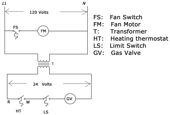
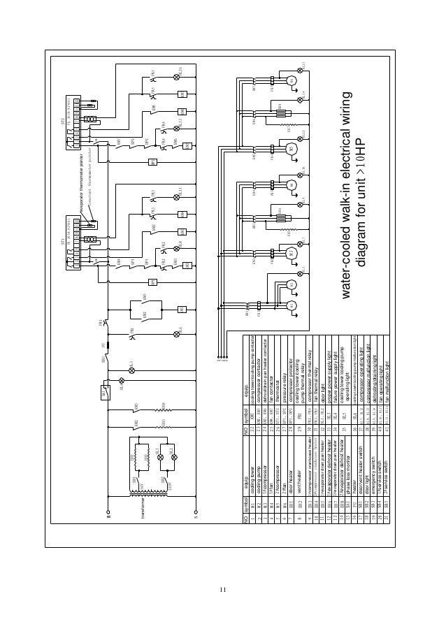
S and Paragon Available in Wiring using V or V single phase line Wiring Diagrams Electric Heat Defrosting S & S Series. •.
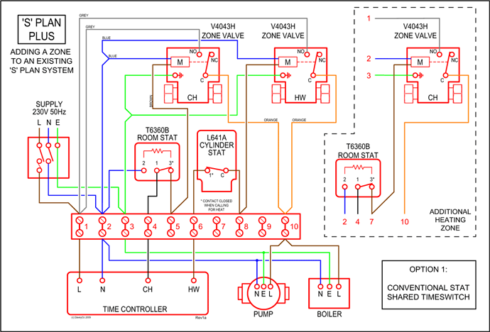
Series Specifications. Uni-Line.
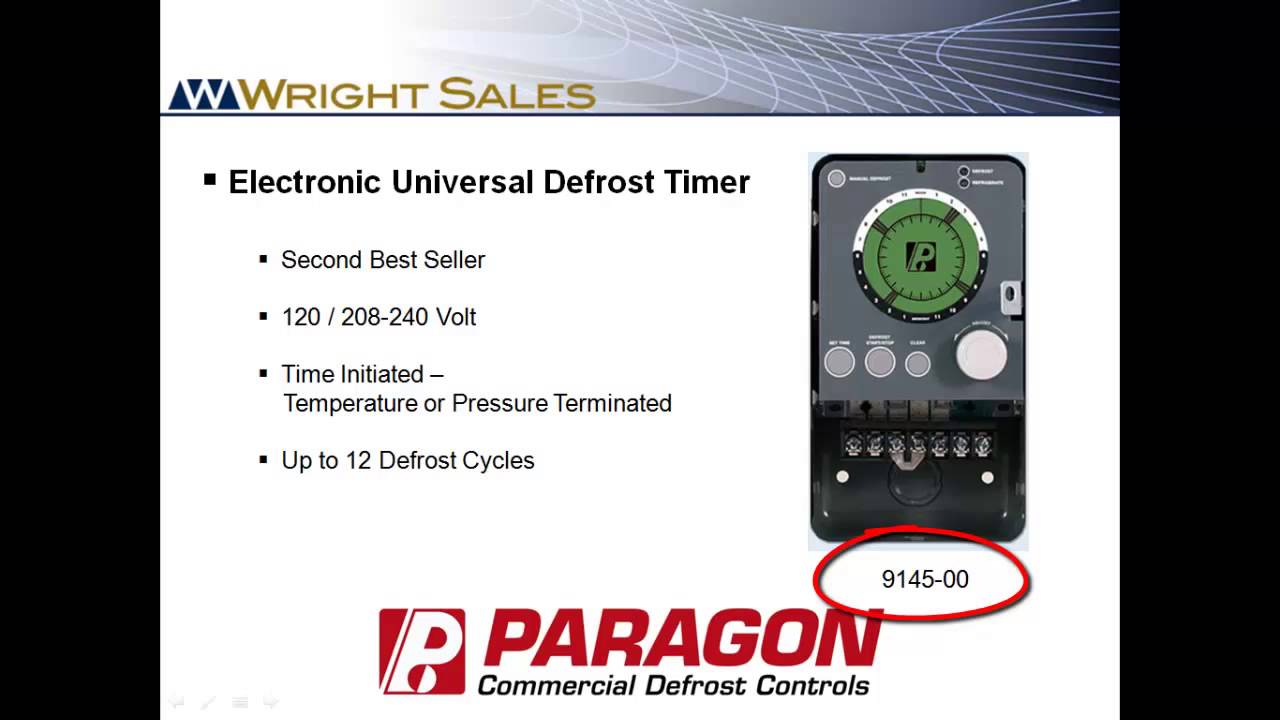
Part No. Volts Hz.
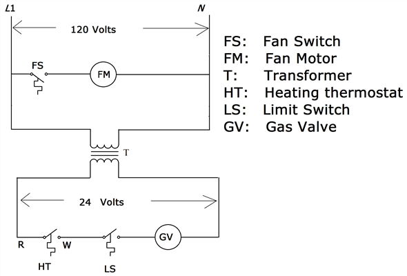
Normal Position of Contacts During Applications and Wiring Diagrams. MECHANICAL. Models , and E -.
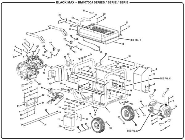
Wiring Diagram. Wiring using V or V single phase line with compressor thermostat closed during defrost. •.
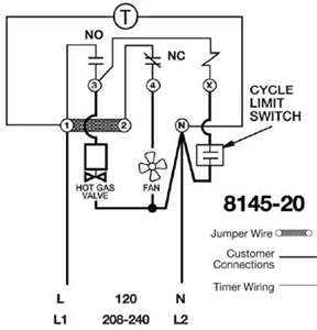
Series Specifications. Uni-Line. Part No.
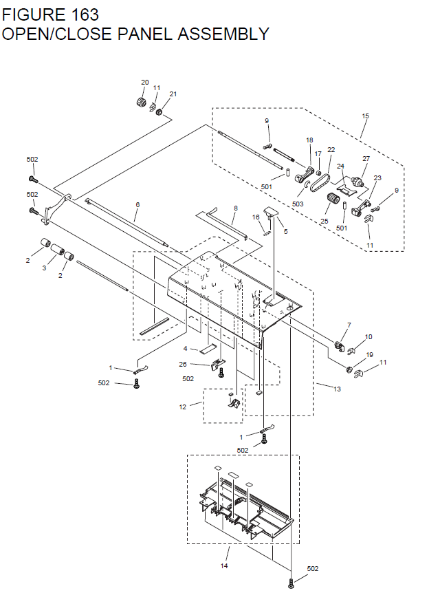
Volts Hz. Normal Position of Contacts During Applications and Wiring Diagrams.
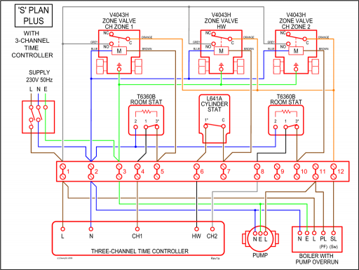
MECHANICAL. how to test paragon 20 defrost timer rh waterheatertimer org Paragon 20 Wiring Schematic Paragon Time Clock 20 Defrost Timer Wiring Diagram – 20 Wiring Diagram.
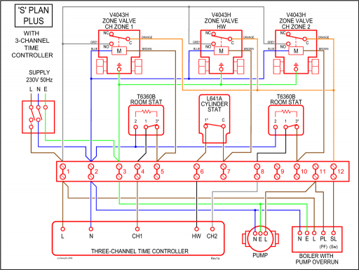
20 Wiring Diagram. On this website we recommend many designs about 20 Wiring Diagram that we have collected from various sites of Free Wiring Diagram Images Gallery, and of course what we recommend is the most excellent of design for 20 Wiring Diagram.
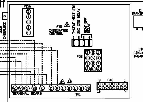
Reviews Manchester Air Conditioning and Heating Services from paragon 20 wiring diagram. The Soul Amounts window has a whole lot of stats, so it’s going to essentially acquire a good deal of time and hard work to max all of them out.
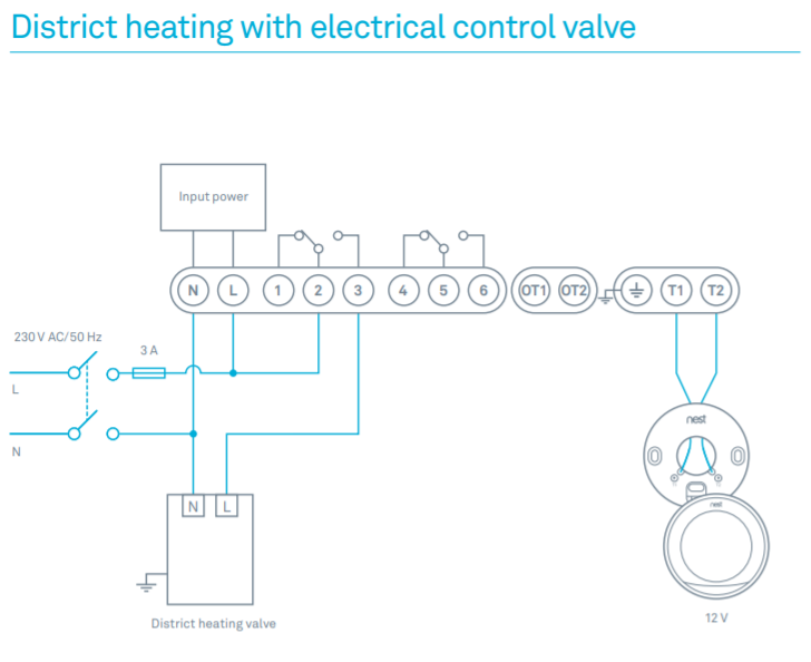
Apr 28, · Open following link to see wiring diagram and manual for Paragon defrost timers: is V time-initiated, pressure or temperature terminated, with back-up time termination. wiring diagram for paragon defost timer & – Paragon Defrost Timer question.
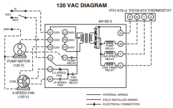
Wiring diagram for paragon defost timer & Posted by saeidr on Jan 28, I need a three phase wiring diagram for model timer. .
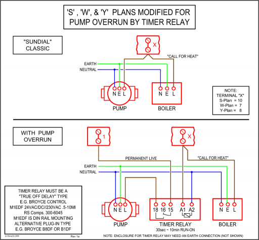
Paragon 20 Wiring Diagram — here you are at our site, this is images about paragon 20 wiring diagram posted by Brenda Botha in Paragon category on Nov 07, You can also find other images like images wiring diagram, images parts diagram, images replacement parts, images electrical diagram, images repair manuals, images engine.Paragon Defrost Timer wiring diagram – Questions (with Pictures) – FixyaSOLVED: Wiring diagram for paragon defost timer – Fixya