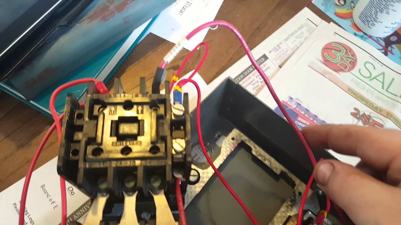
Can anyone help me find any diagrams of wiring the motor controls. humberguy is offline is this a self-contained unit where the START and STOP buttons are built into the starter/contactor, or are the buttons a seperate unit?
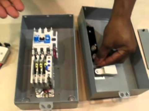
emolatur is offline push button for stop. One relay for control, and the motor.
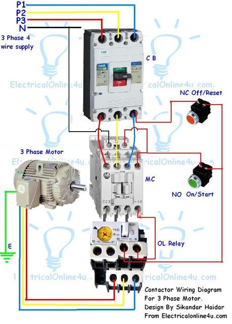
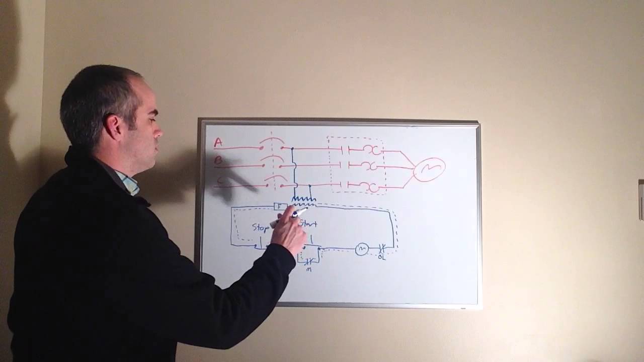
START-STOP CONTROL WIRING DIAGRAMS. Single Station with the starter.
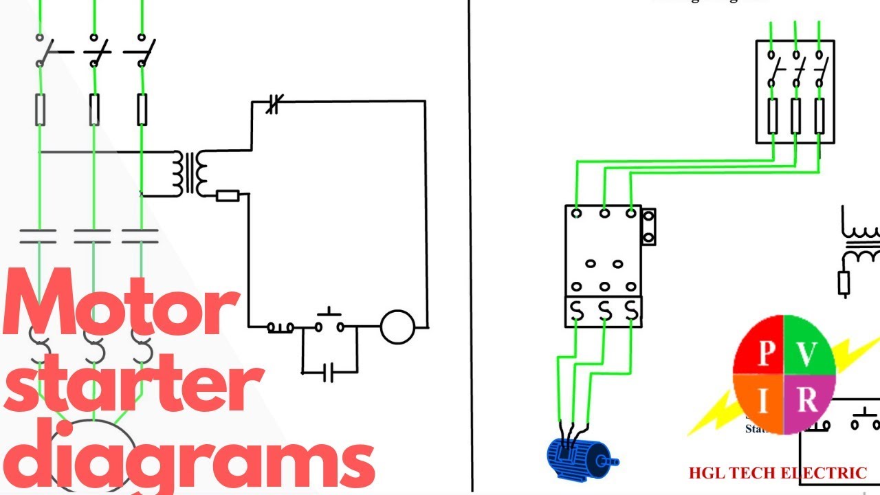
Motor Starter Wiring Diagrams
. PUSH BUTTON STATIONS.
Motor Controls: Basic Start/Stop Circuit
I. Voltage.
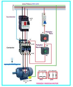
V. v.
V 60Hz. V 60Hz.
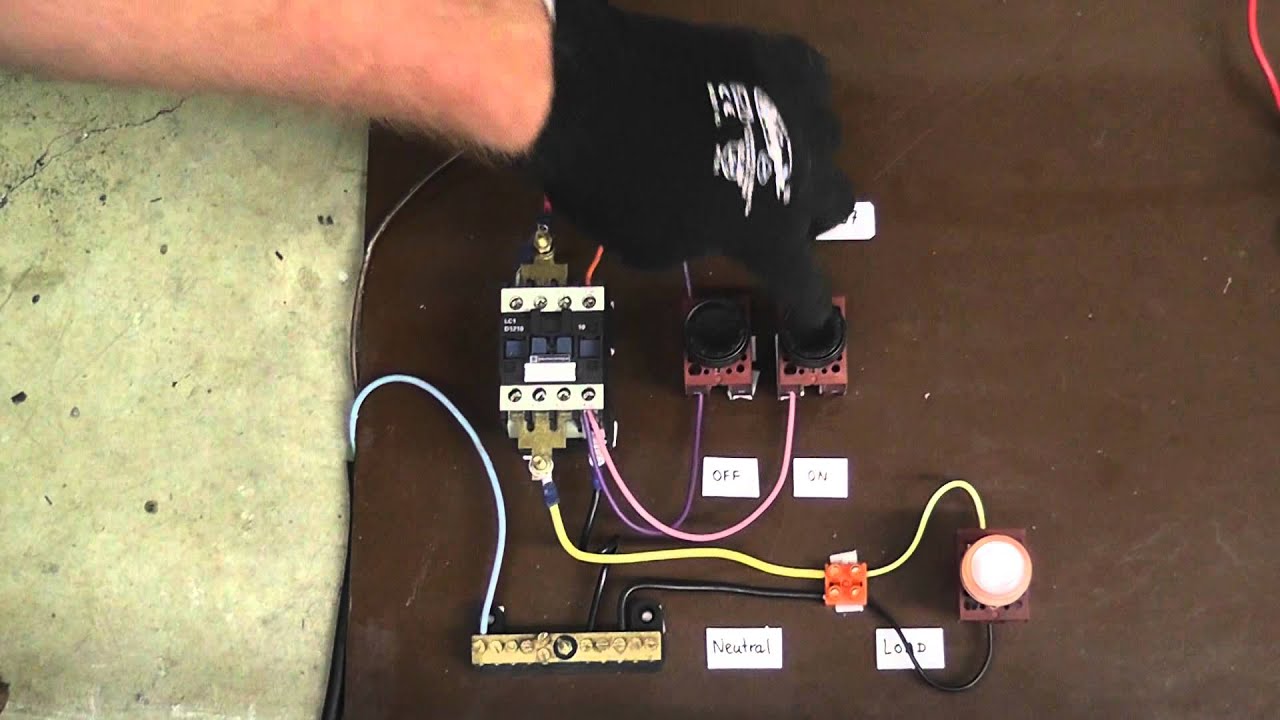
Air Compressor or Float Pump/3ph Starter/1ph Motor Magnetic Starter – Control Stations . START Button must be wired in Parallel to one another; STOP Buttons If you have a V coil, instead of running a line from Coil.

Air Compressor or Float Pump/3ph Starter/1ph Motor Magnetic Starter – Control Stations . START Button must be wired in Parallel to one another; STOP Buttons If you have a V coil, instead of running a line from Coil. Start Stop 3 Phase Motor Starter Wiring.
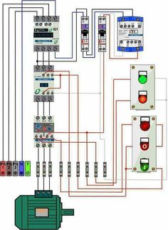
Thomas Shue’s World. Loading Unsubscribe from Thomas Shue’s World? Cancel Unsubscribe.In the above one phase motor wiring i first connect a 2 pole circuit breaker and after that i connect the supply to motor starter and then i do cont actor coil wiring with Normally Close push button switch and Normally Open push button switch and in last i do connection between capacitor.
v delta wye transformer wiring diagram together with. Typical Wiring Diagrams For Push Button Control Stations 3 Genera/ Information @ Each circuit is illustrated with a control circuit (continued) schematic or line diagram and a control station wiring diagram. l The schematic or line diagram includes all the components of the control .
Motor Wiring Diagram With Start And Stop – phase wiring diagram moreover 3 v in addition 3 phase motor wiring diagrams moreover index2 also 3 phase motor wiring diagram also wiring a 3 phase motor starter also wiring diagram for a start stop station moreover vac motor starter diagram also 3 phase v e stop wiring diagram furthermore wire diagram v contactor v . In the above one phase motor wiring i first connect a 2 pole circuit breaker and after that i connect the supply to motor starter and then i do cont actor coil wiring with Normally Close push button switch and Normally Open push button switch and in last i do connection between capacitor start motor .
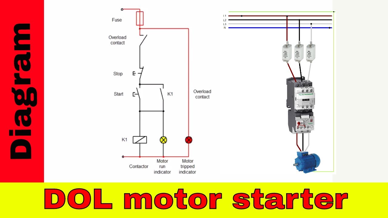
The most common use of 3 wire control is a Start/Stop control. See image below for an example of 3 wire control being used to pull in a contactor to start a 3 phase motor. When you press the start button and the stop button is not pressed, the 24VDC relay energizes and it pulls in the R1 contactor that feeds three phase power to the motor.Motor Starter Wiring Diagrams – schematron.org Knowledge Base (Wiki)Motor Starter Wiring Diagrams – schematron.org Knowledge Base (Wiki)
