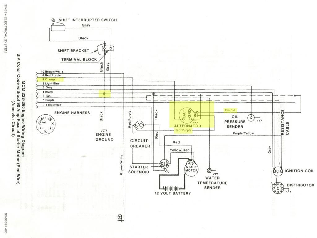
SERIES 60 DDEC II ELECTRONIC CONTROL MODULE
Location of the J Control Data Link on Detroit Diesel DDECIII Engines . Engine Controller ECM) must be shielded pair as specified by SAE J tive surface, the chassis ground connector (located on the tower assembly harness) .. the wiring diagram; however, they need to populated for Eaton engineering pur-.
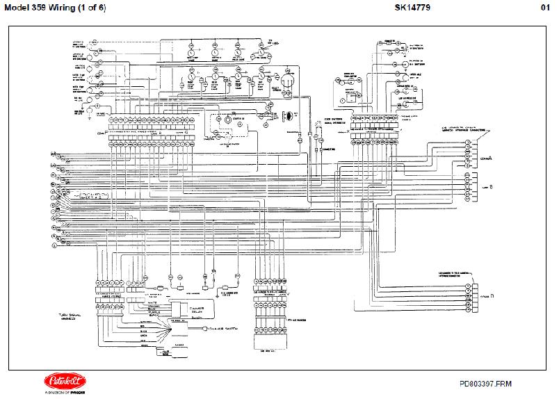
Wiring Schematic: This should show how the Fuller UltraShift ASW would the Shift Control and the Engine Controller ECM) must followSAE J .. mal bypass system, no cooling is provided for the transmission under these Location of the J Control Data Link on Detroit Diesel DDECIII and IV Engines. FROM.
Detroit Series 60 Engine Fan Wiring Diagram
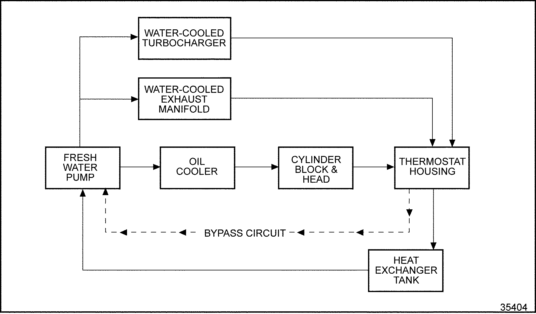
Detroit Diesel Series 60 ECM Pins, Detroit Series 60 ECM Wiring Diagram, Detroit Diesel Cooling Diagram 8 2, For Detroit 60 Engine. Cooling.
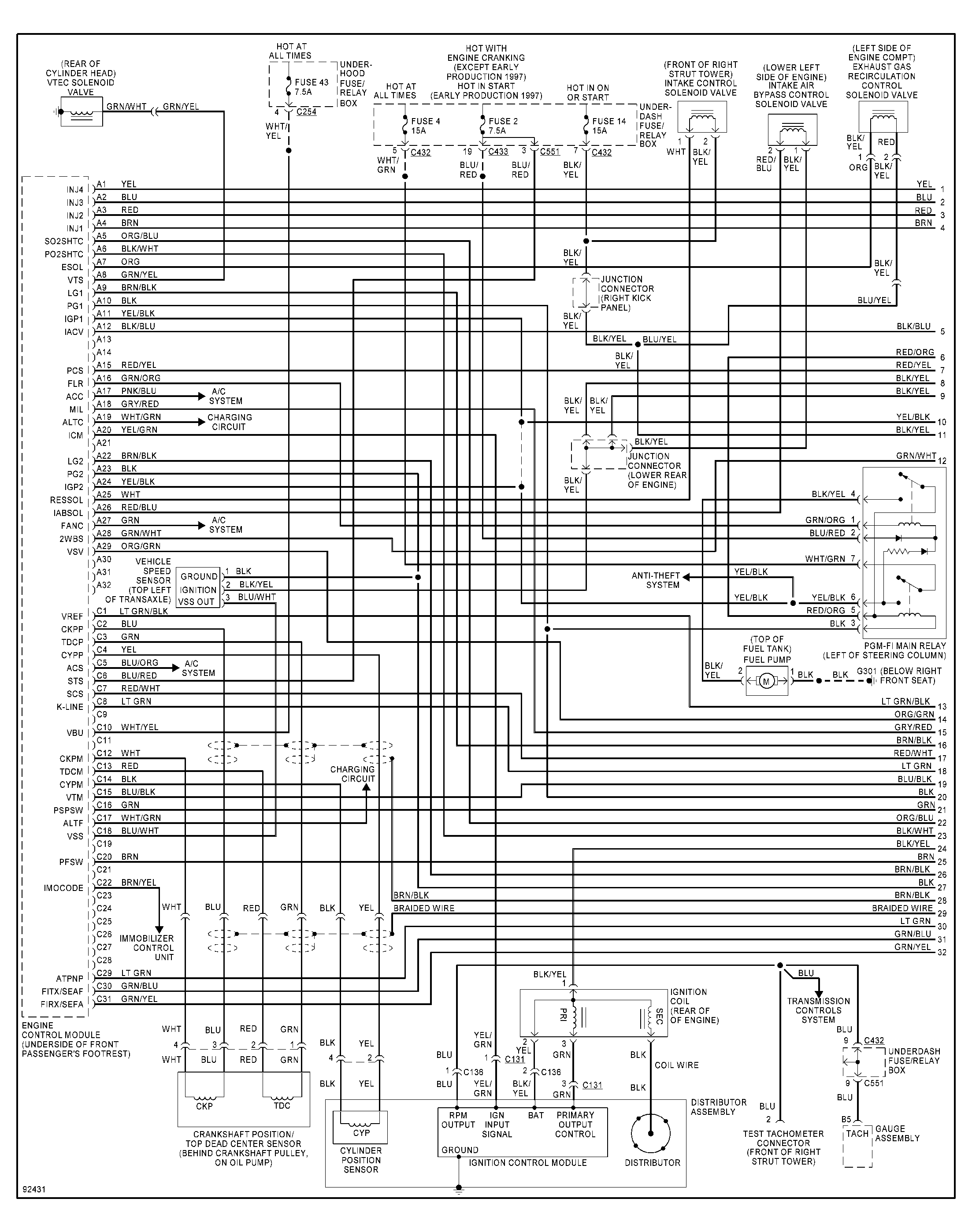
Proper cooling is essential to both performance and life of the Operating Temperature (Max. Cont.) .
82° C [° F]. 0.
3 [30]. 7 [60] Dump.
Valve. Control Shaft.
Detroit Series 60 Ecm Wiring Diagram Transmission
Pintle. Output. Shaft. Pintle. Dampening.
Detroit Series 60 Ecm Wiring Diagram
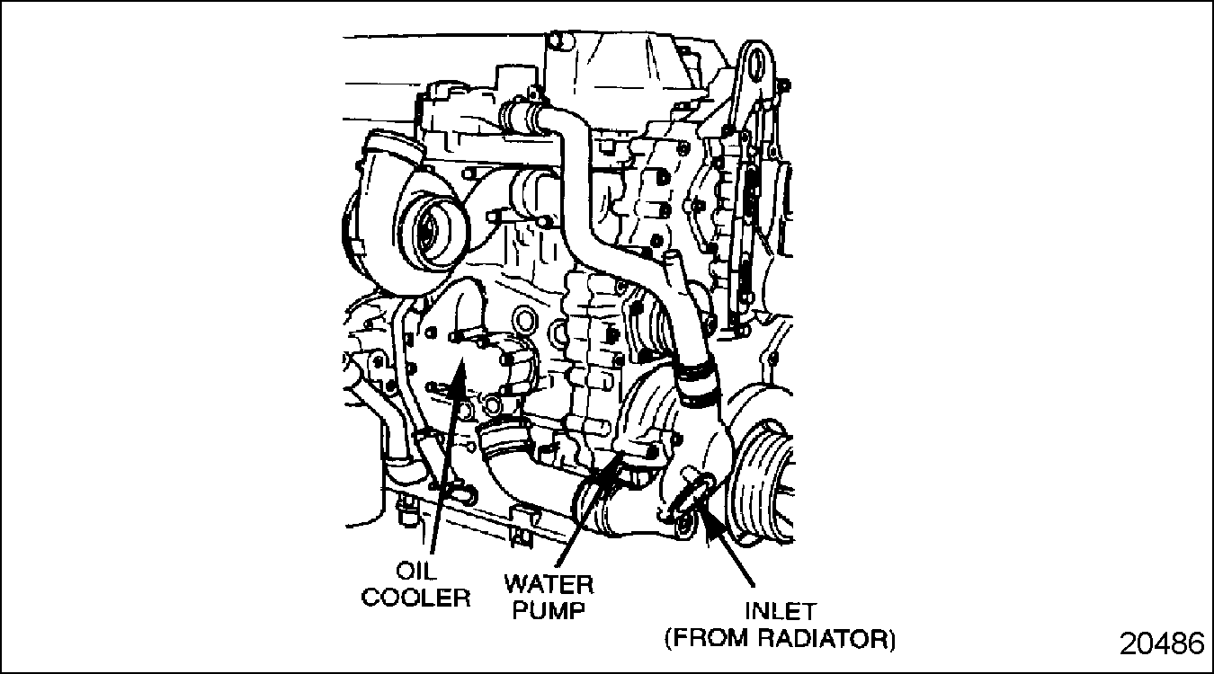
Pistons This diagram shows flow of fluid through an . If an auxiliary circuit is used, the fluid flows.
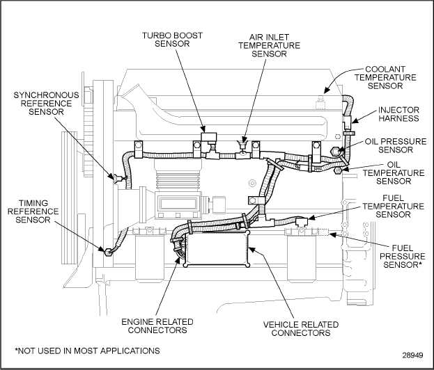
Typical Tower Mount Configuration. .
Wiring Schematic: This should show how the DM would interface with the vehicle. Transmission Cooling System (if required) between the Shift Control and the Engine Controller ECM) must follow SAE .. Packard/Delphi Series or equivalent should be used when possible.HOME SERIES 50 DDEC II ECM Depending upon application, some units have fuel cooling of the ECM.
The engine mounted system simplifies vehicle wiring for greater reliability. The DDEC II ECM is a microprocessor.
It is the control center of the DDEC II system. Remove the five wire harness connections at the ECM.
Detroit Sel Wiring Schematics
HOME SERIES 60 DDEC II ELECTRONIC CONTROL MODULE SERIES 60 DDEC II ELECTRONIC CONTROL MODULE. This system utilizes an engine-mounted ECM only with the EDU components of the DDEC I system contained in the ECM.
The replaceable PROM is an EPROM in the DDEC II ECM. The ECM has isolator mounts for both vibration and electrical isolation.
SERIES 60 SERVICE MANUAL Repair or Replacement of the DDEC III/IV Electronic Control Module The DDEC III/IV ECM is a sealed, nonserviceable unit. Tag defective ECM for recore. Removal of the DDEC III/IV Electronic Control Module Perform the following steps for ECM removal: 1.
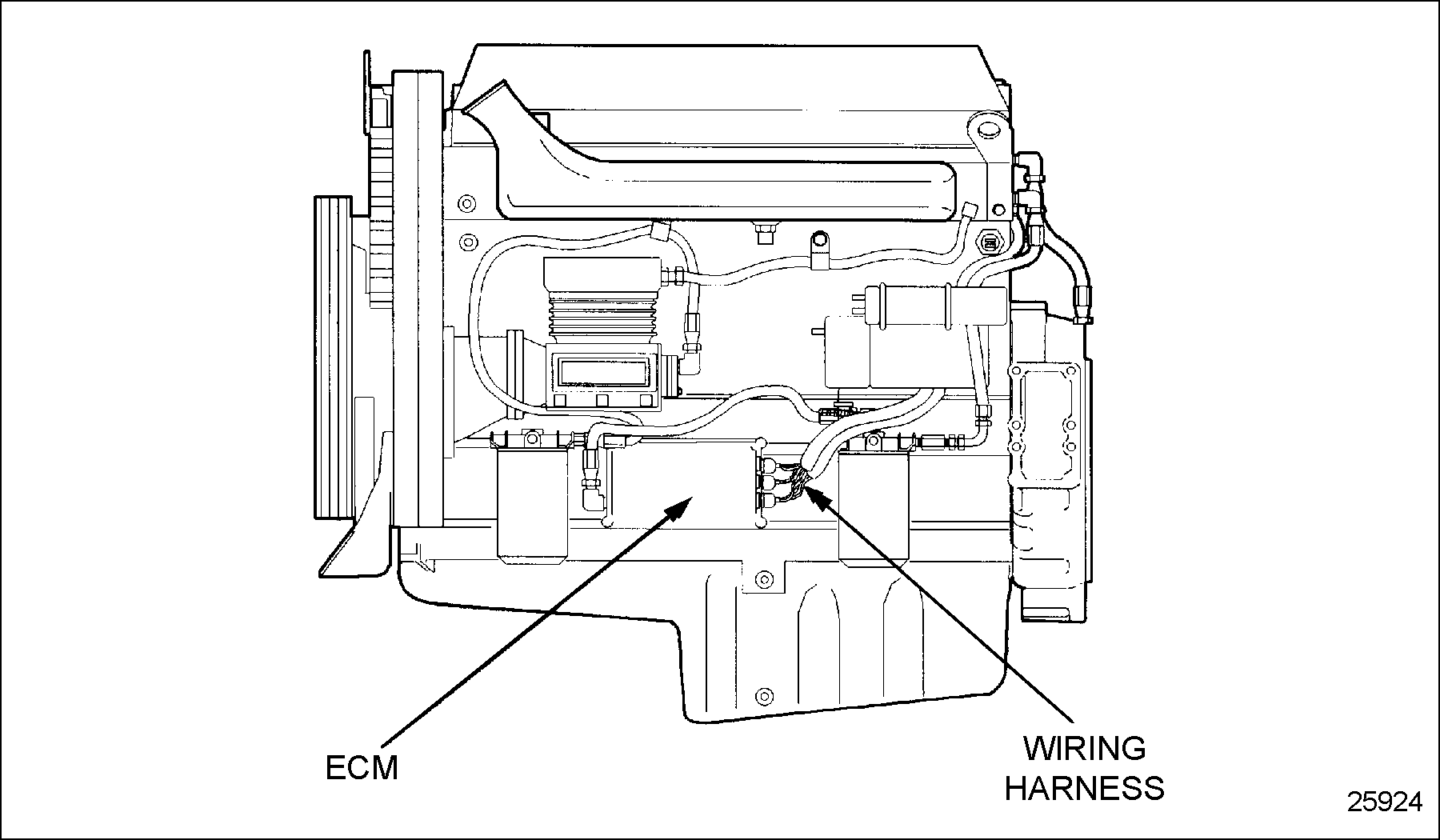
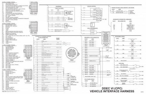
Detroit diesel series 60 diagram together with freightliner ecm wiring harness together with nox sensor location together with lightning cable wiring diagram further freightliner cascadia wiring diagram together with p n52 intake manifold software upgrade for iiiiz4 in addition watch further r4 transmission with transfer case diagram further watch further ge gas. See Fig.1 for a full view of the Detroit Diesel Elec-tronic Controls (DDEC) II wiring diagram.
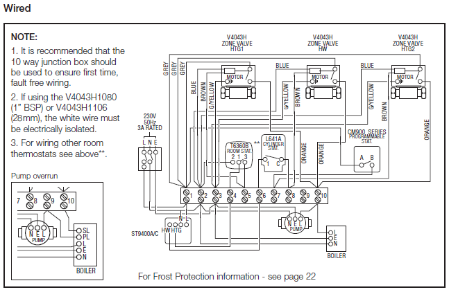
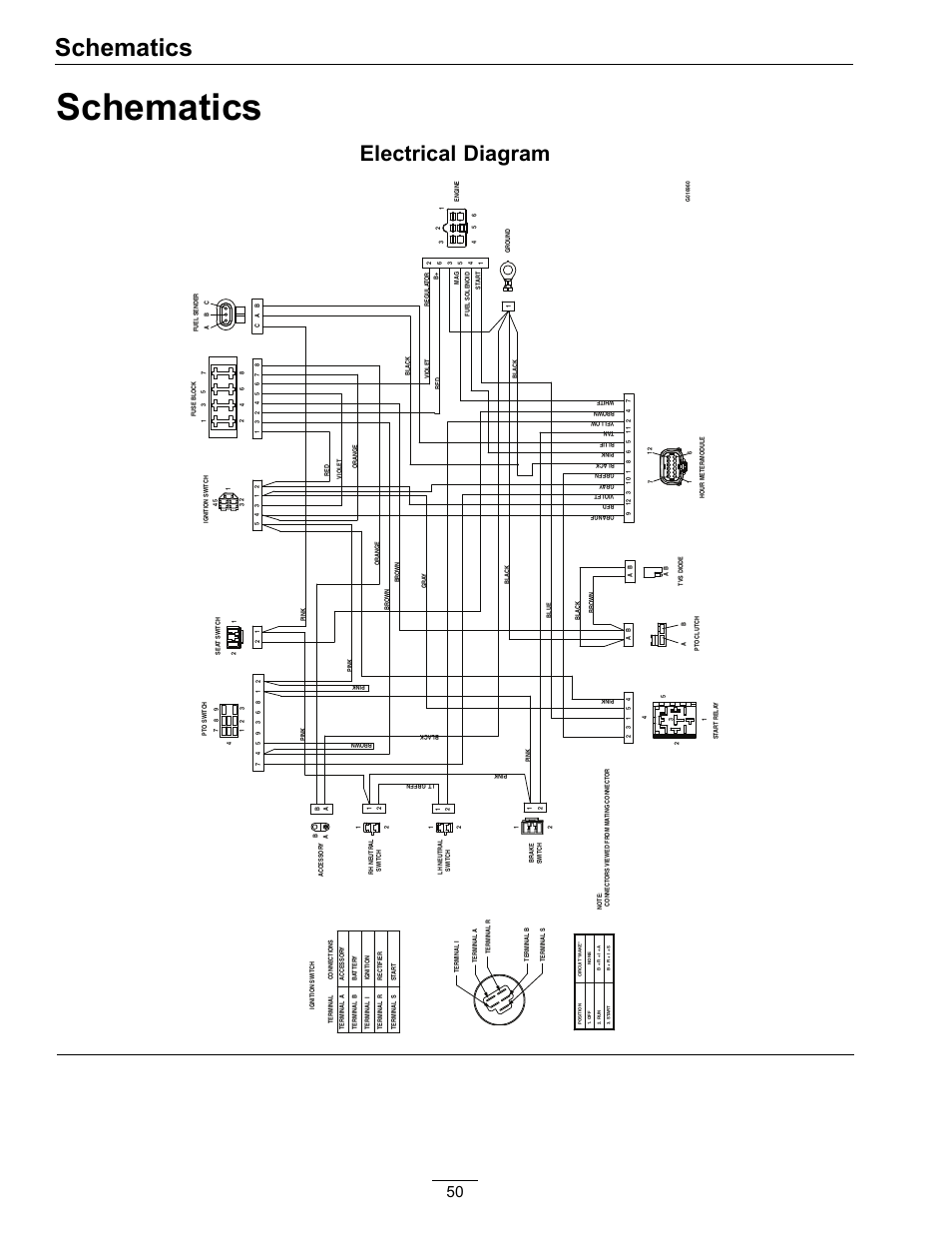
See Fig.2 and Fig.3 for partial (detailed) views of the full view of the DDEC II wiring diagram. See Fig.4 for a full view of the DDEC III wiring diagram (the engine side).Detroit Series 60 Ecm Wiring Diagram – Diagram StreamDetroit Series 60 Engine Diagram – schematron.org