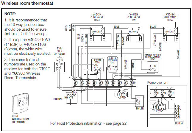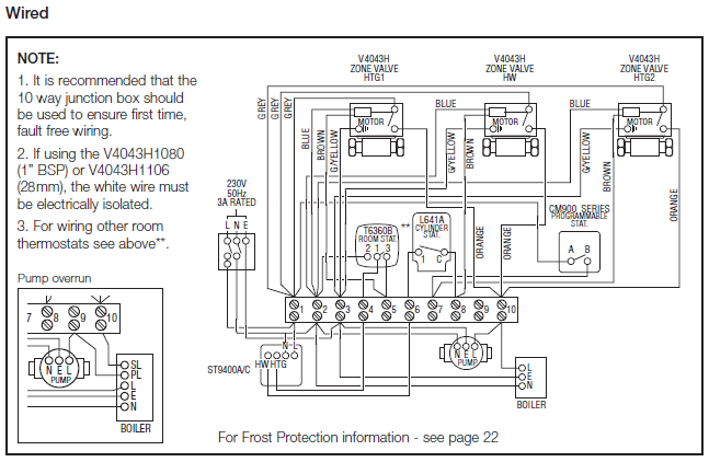
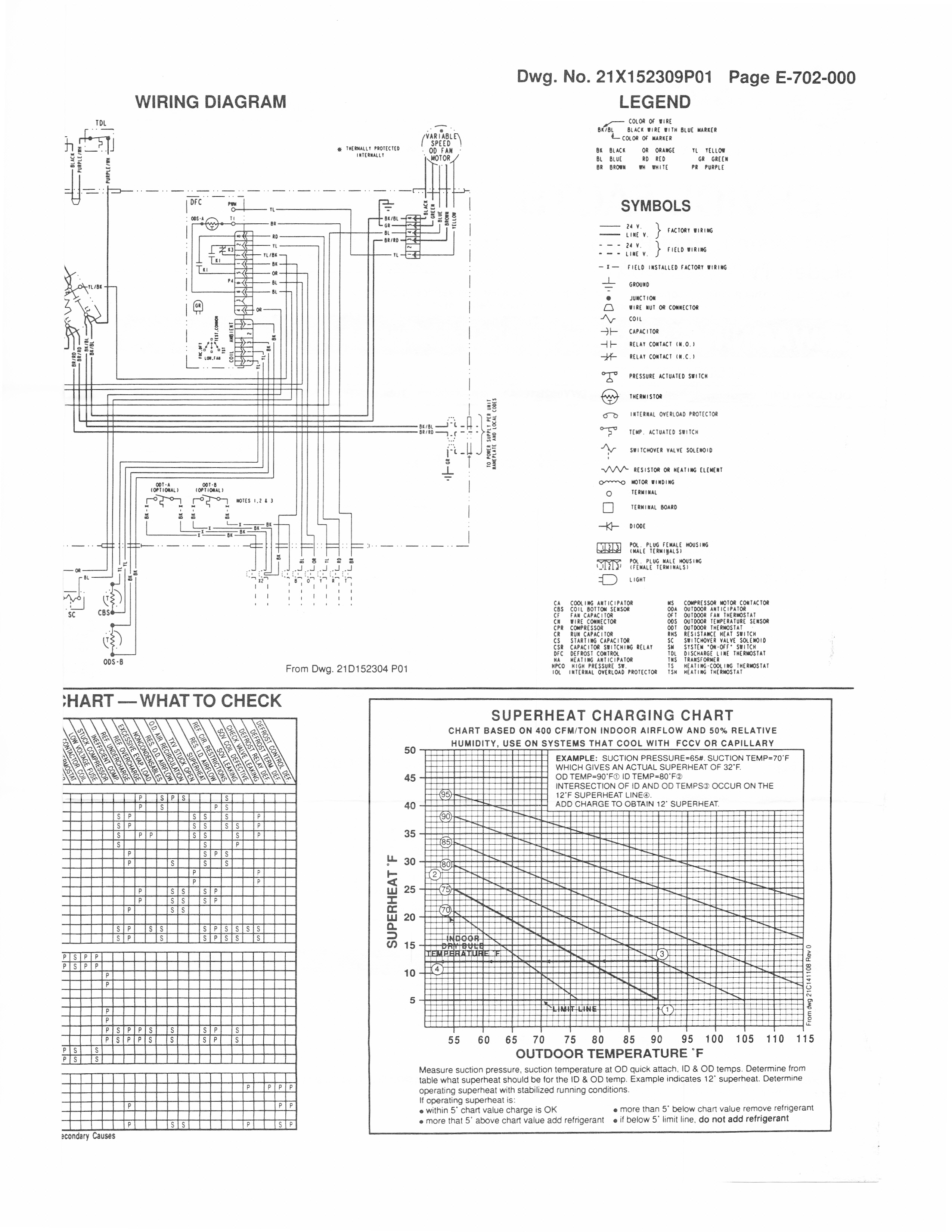
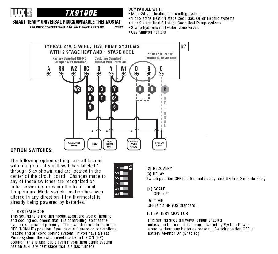
This diagram is to be used as reference for the low voltage control wiring of your heating and AC system. Always refer to your thermostat or equipment.
BC62D ALL phases of this installation must comply with NATIONAL, STATE AND LOCAL CODES .. Heat Pump. Black.
W1. W2. W3.
G . 24V AC between Y & B with unit operating.
Follow instructions on unit wiring diagram located. ALL phases of this installation must comply with NATIONAL, STATE AND LOCAL CODES Heat Pumps ..
24V AC between Y & B with unit operating. • Defrost. Digital Round Thermostat Honeywell YH – Heat Pump Y-Pack Honeywell Typically a thermostat wire pull is made to the air handler on split systems and If you have a Trane, Carrier, Goodman, Lennox, Ducane, Heil, Fedders. Typical systems that do not use volt control are window unit air conditioners, ductless Air Conditioner Control – Thermostat Wiring Diagram – HVAC Systems.The yellow wire is connected to the coil on the cooling contactor, and the other end is connected to the Y terminal on the thermostat.
The white wire is connected to the relay for the electric heat, or the gas valve.
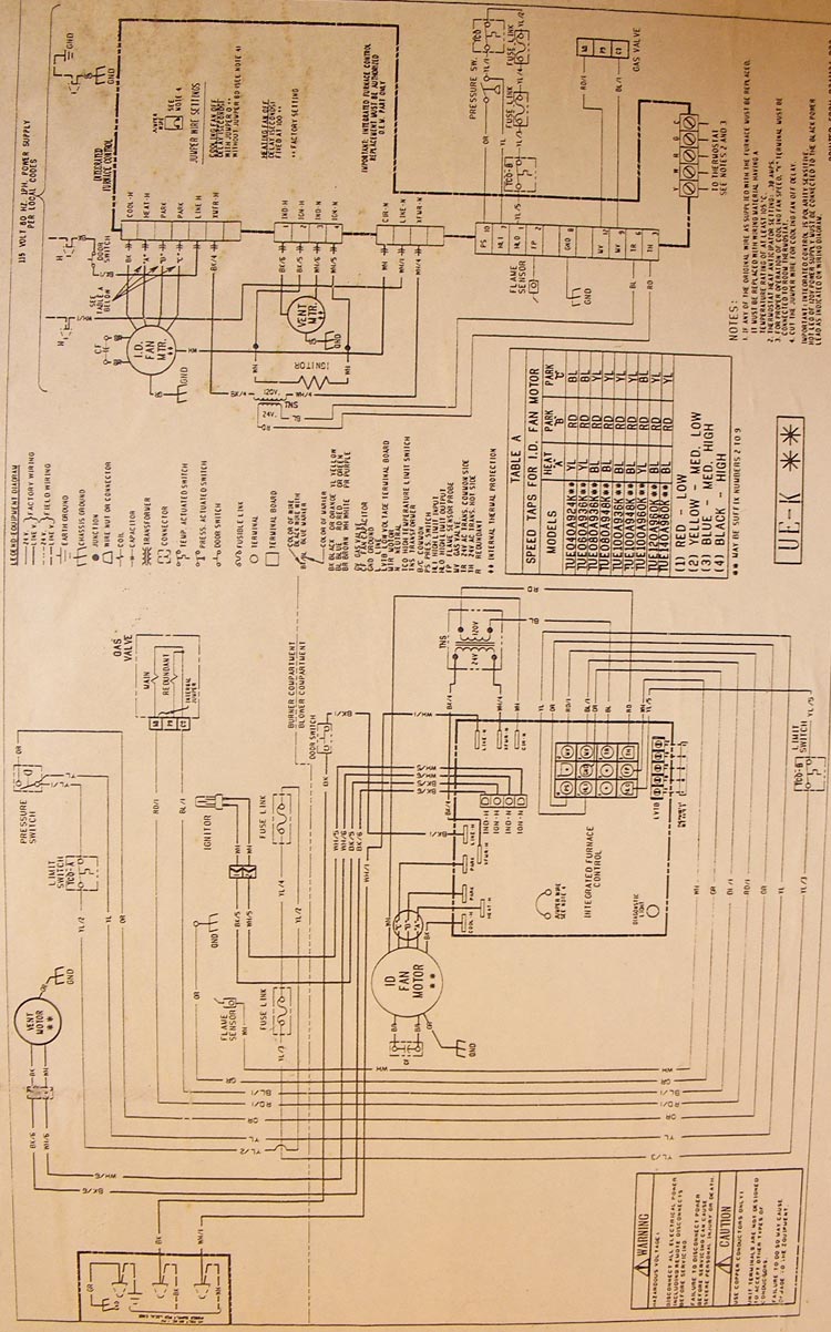
The green wire is connected to the fan relay and connected to the G terminal on the Trane thermostat. Trane Heat Pump Thermostat Wiring Diagram – Gooddy, size: x px, source: schematron.org Whatever you are, we attempt to bring the web content that matches just what you are seeking. AC Heat Pump with Variable Speed Air Handler and Two Stage Electrical Backup Heat Control Wiring Some AC Systems will have a blue wire with a pink stripe in place of the yellow or Y wire.
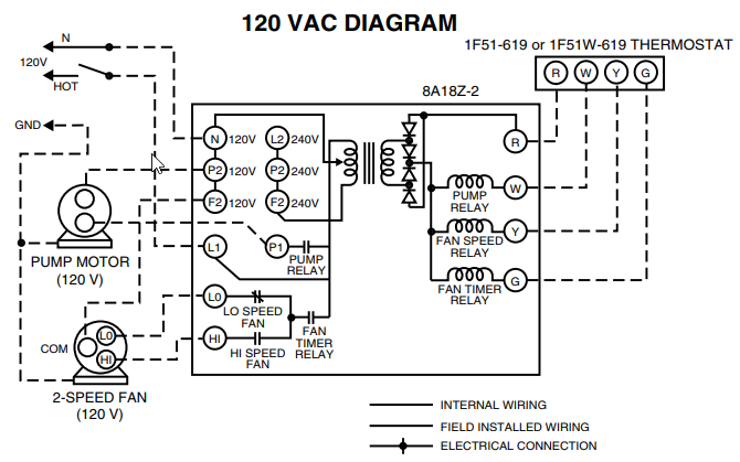
24 volt secondary transformer Selection Procedure • Low voltage wire nut connections • Insulated cabinet • Uses series heaters • External access to heater circuit breakers • Polarized plugs for making electrical connections from air handler control box to heaters • Approved for modular or manufactured homes UNIT PARTS. For the thermostat wiring colors code for this terminal (if equipped) consult with the installer.
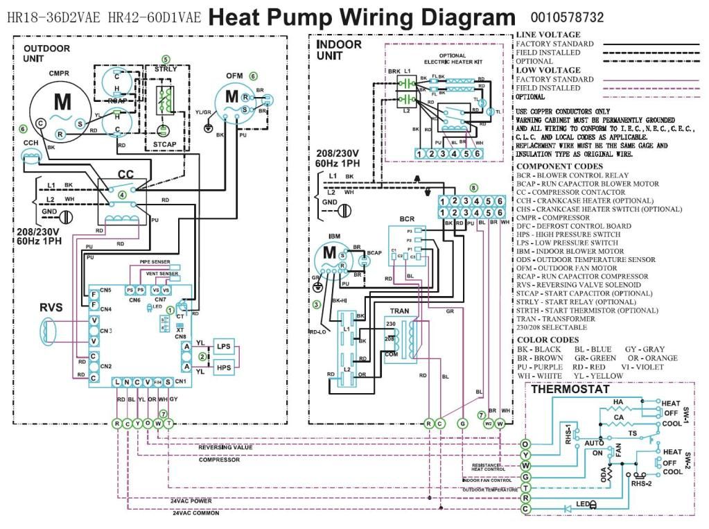
If that is not possible then trace the wire out to the source. O or B – These terminals are for heat pumps and the B tstat terminal is used on for Rheem or Ruud and any manufacturer that energizes the reversing valve in heating mode for the heat.Heat Pump Thermostat Wiring DiagramTrane Heat Pump Wiring Diagram Schematic – schematron.org
