Large condensing units, remote condensers, and evaporators should be left on their shipping System wiring diagrams are located inside the condensing.
V Series. • Sierra Piping Schematic . installation time, and takes the guess work out of selecting components.
Sierra™ Copper finned condenser and evaporator coils .. RIH H22 (1) AE B Thomas French Drive, Scottsboro, AL PHONE () FAX () russell. schematron.org Motor Cross-Reference Chart following example applies to Russell evaporators, with the exception of ASL and SL models which AEB, AE 46B .
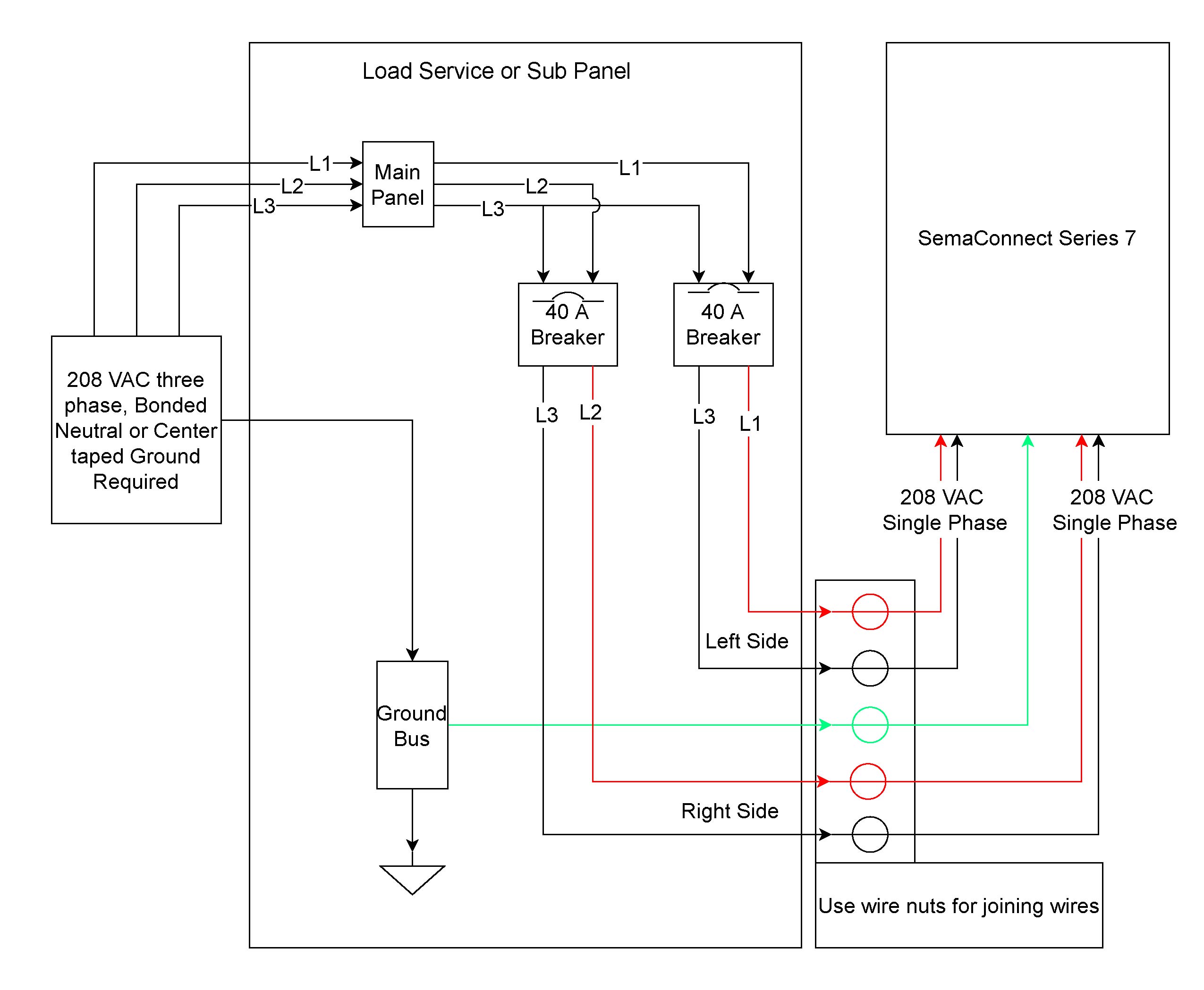
HEATER SAFETY SWITCH, 2 WIRE. AE A system wiring diagram is located inside the condensing unit control box. Air defrost systems are wired so that the evaporator fans run continuously.
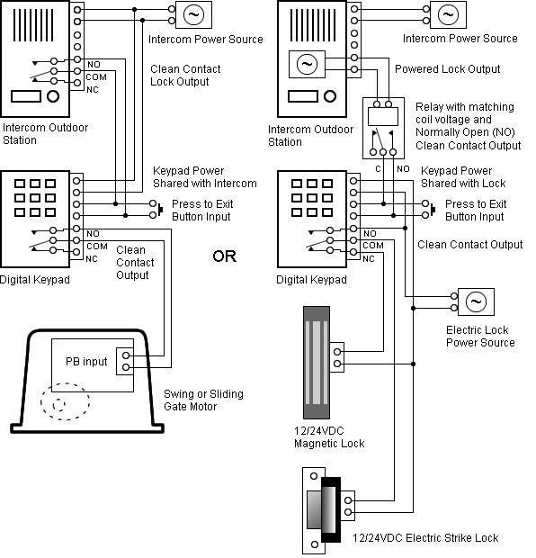
Sierra and High Sierra condensing units include Russell’s patented finned receiver®, .. 1 – 6 FAN AE MODELS AEB, AEB, AEB, AEB AE 72B. A system wiring diagram is located inside the condensing unit control box.
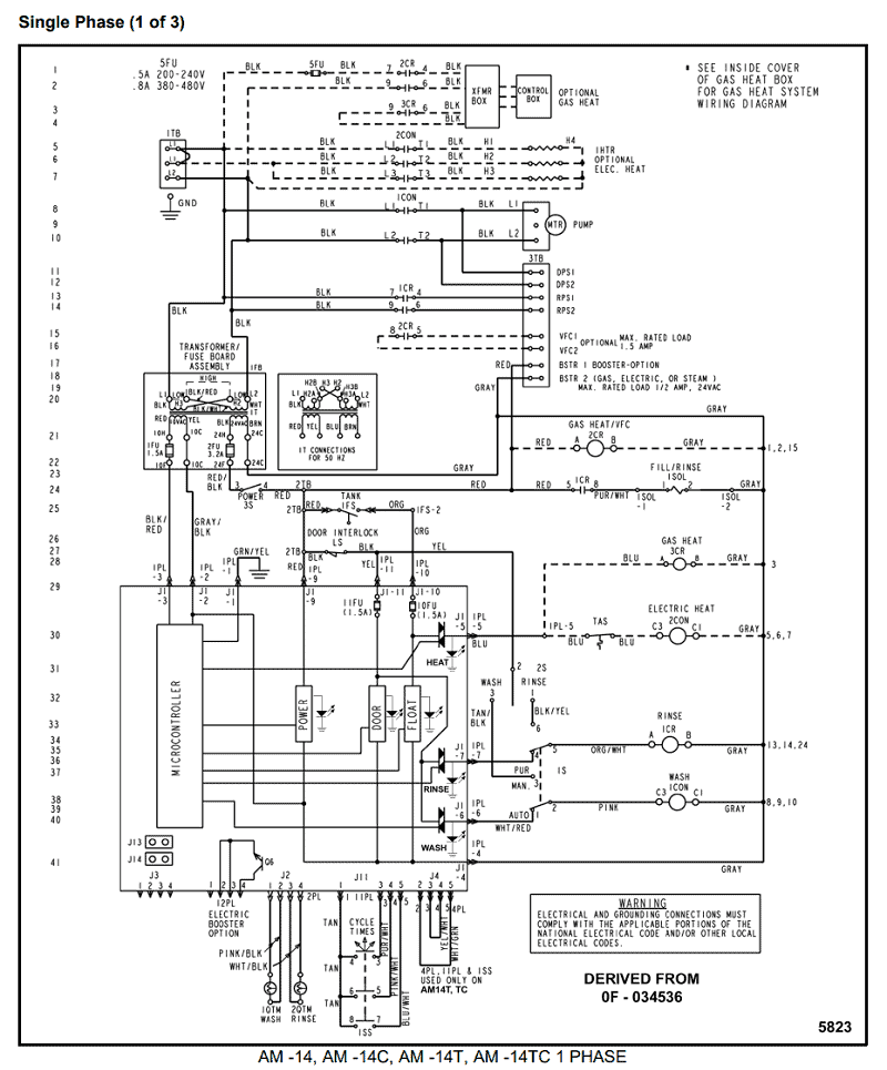
Air defrost systems are wired so that the evaporator fans run continuously. Sierra and High Sierra condensing units include Russell’s patented finned receiver®, .. 1 – 6 FAN AE MODELS AEB, AEB, AEB, AEB AE 72B.Collection of russell evaporator wiring diagram.
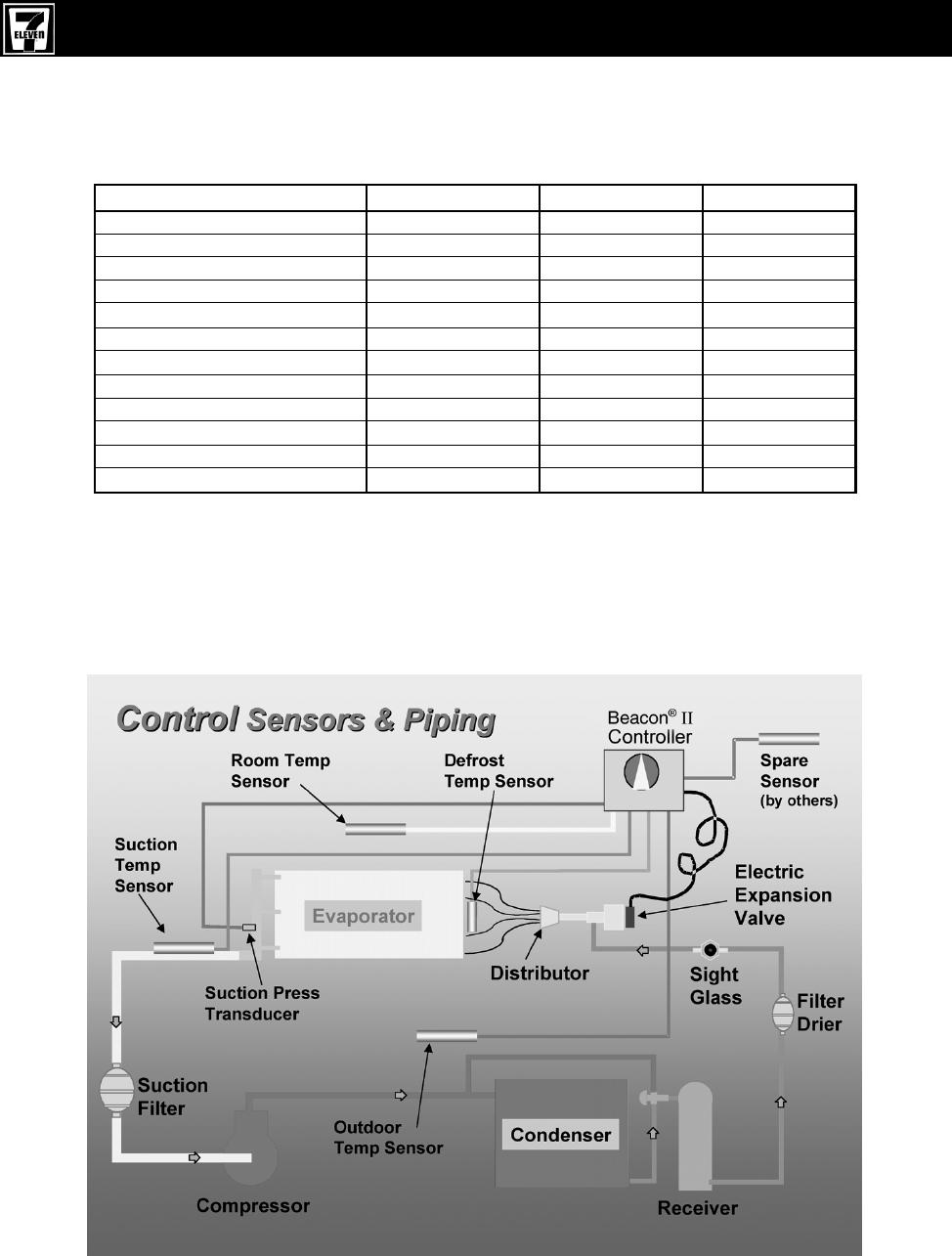
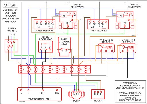
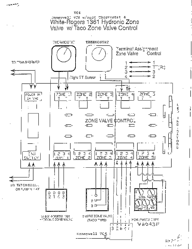
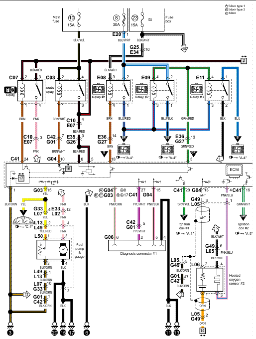
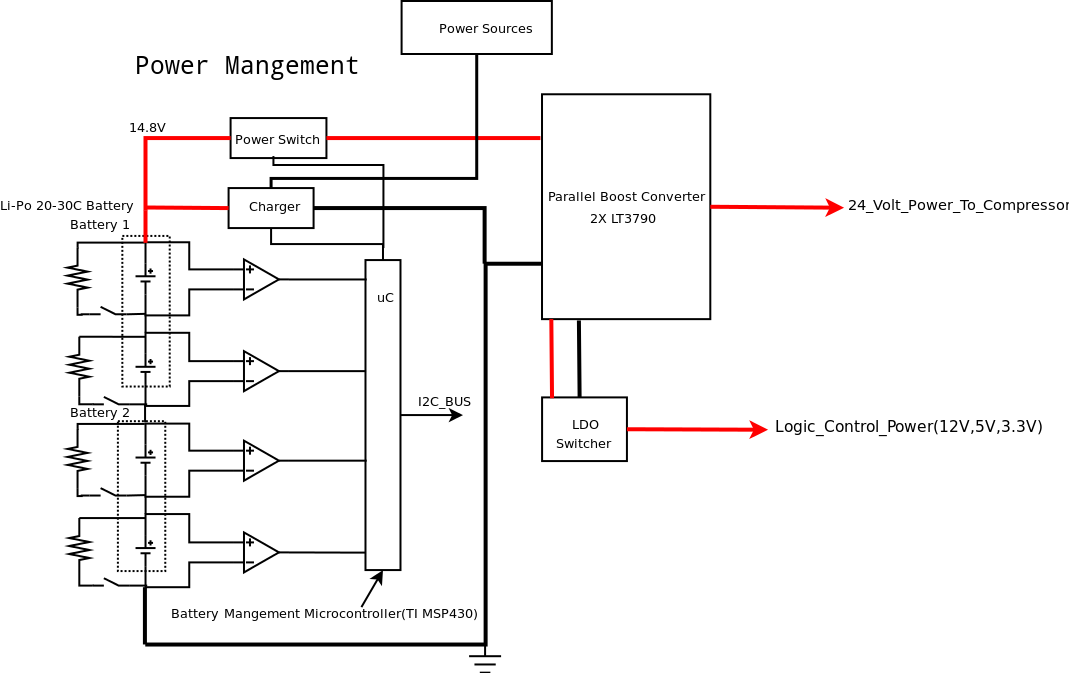
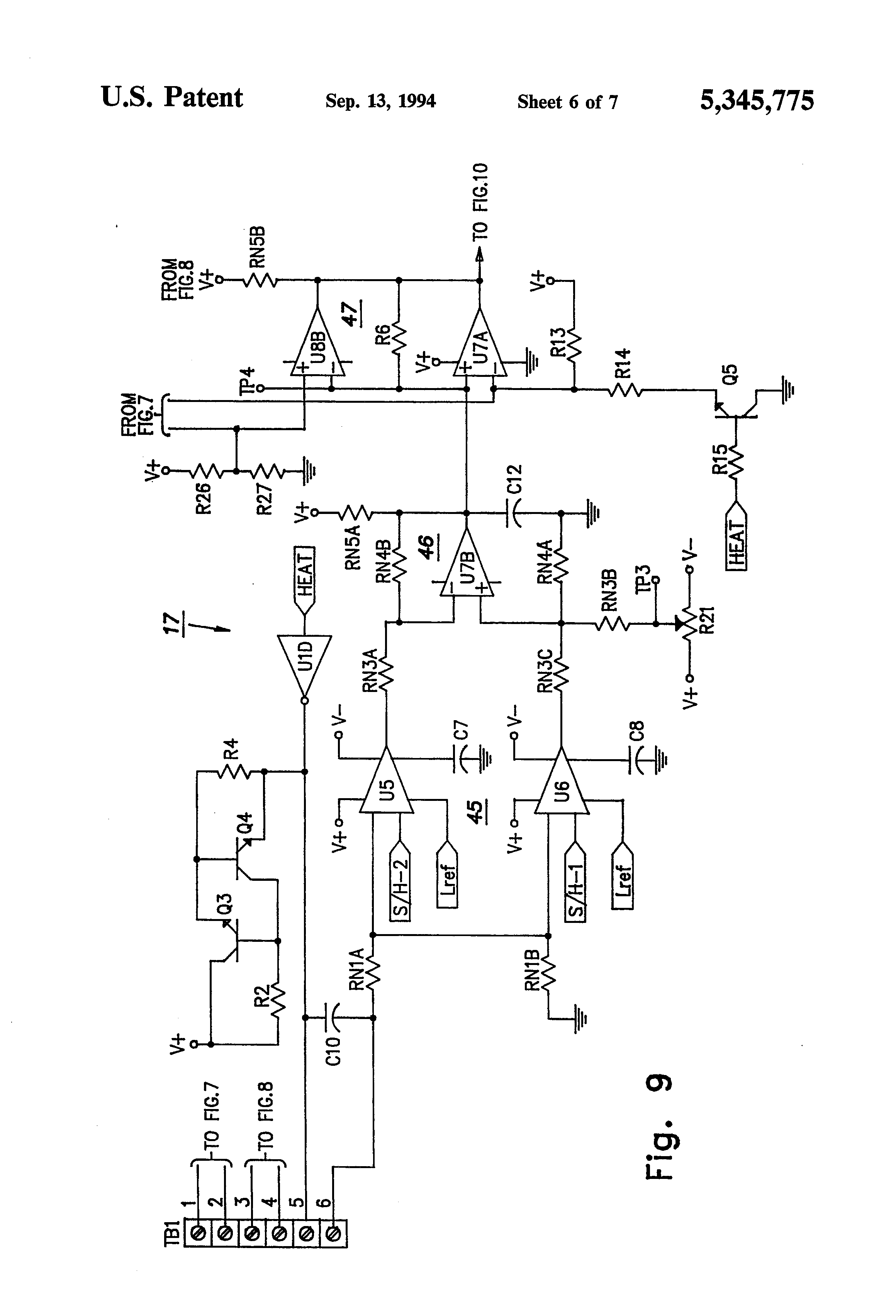
A wiring diagram is a simplified traditional pictorial representation of an electric circuit. It reveals the parts of the circuit as simplified forms, and also the power as well as signal connections in between the tools.
russell evaporator wiring diagram – A Novice s Guide to Circuit Diagrams A very first look at a circuit diagram might be confusing, but if you could read a train map, you could read schematics. The purpose is the very same: obtaining from factor A to point B.
Literally, a circuit is . contact// kold pack, inc. page avenue jackson, michigan custom coolers, llc. azle ave.
fort worth, texas following example applies to Russell evaporators, with the exception of ASL and SL models which have their defrost designation in the suffix position. Designates Product Line Motor Type: E = EC motors AEB, AEB DEFROST HEATER, DRAIN PAN, WATTS, 21″ LENGTH, / V.

Follow the system wiring diagram (provided in the condensing unit). Connection to TB must be made to assure proper pumpdown function.

The room thermostat is mounted on the unit cooler for single evaporator systems and supplied loose for multiple evaporator systems. Follow the system wiring diagram supplied in the condensing unit.INSTALLATION, OPERATION AND MAINTENANCE MANUAL | schematron.orgRussell Evaporator Wiring Diagram | Free Wiring Diagram
