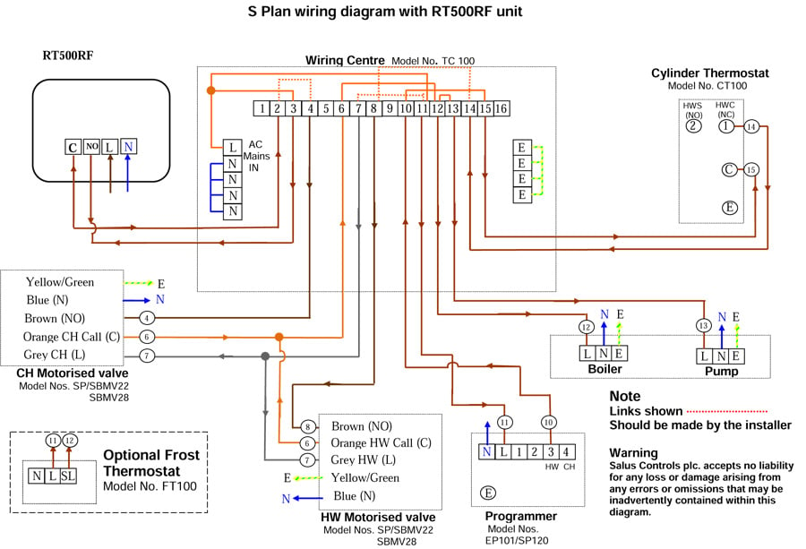
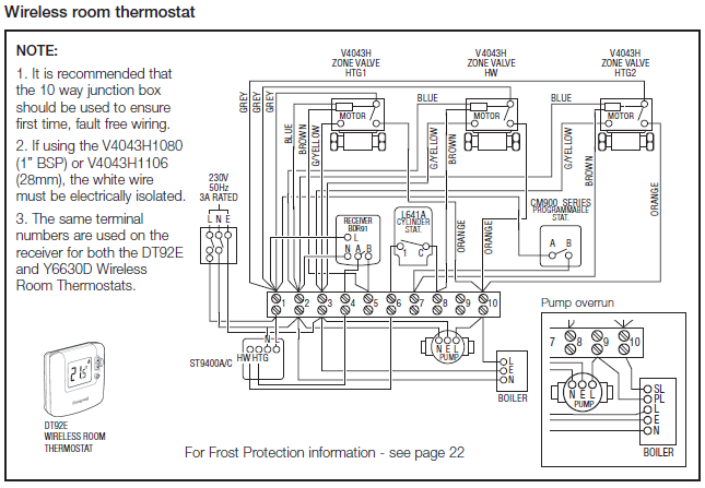
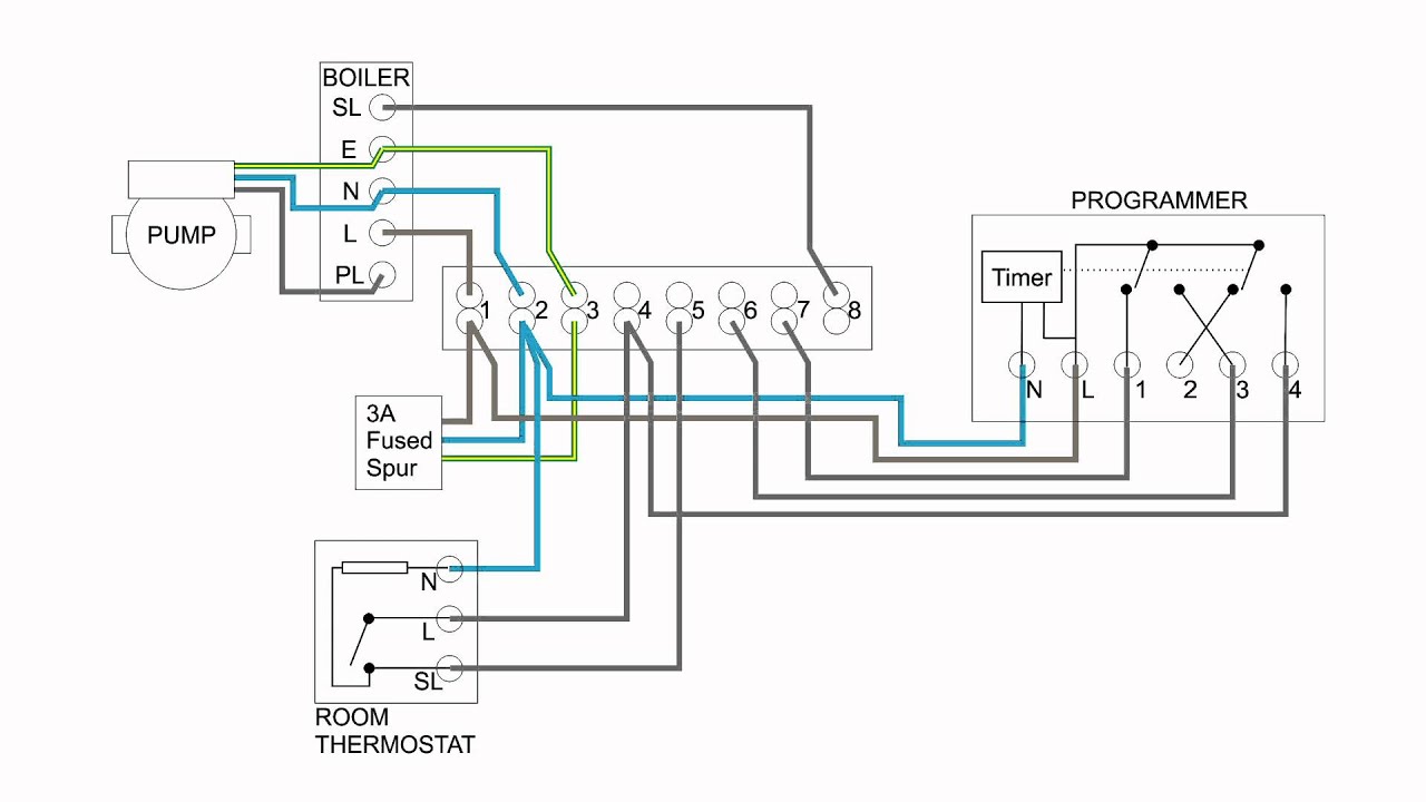
S Plan wiring diagram with RF unit.
C. 1. 2.
E. 1 2 3 4 5 6 7 8 9 10 11 12 13 14 15 E.
E. E. E.
N. Programmer. Model Nos.
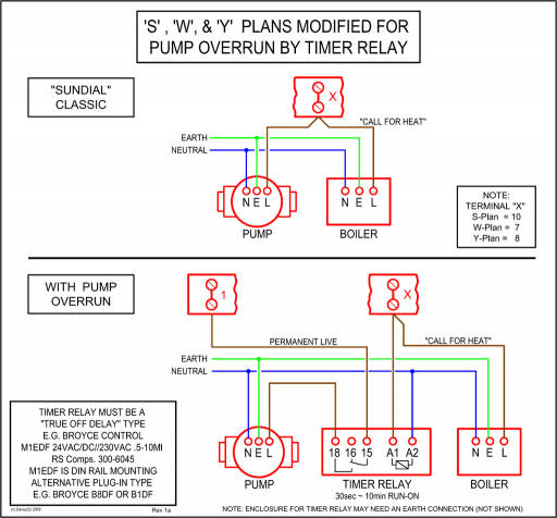
EP/SP Cylinder Thermostat. Got an S plan to wire next week Reading through the wiring diagram and it shows a permanant supply to the boiler along with a switch feed.
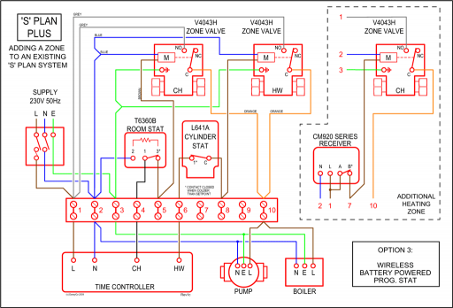
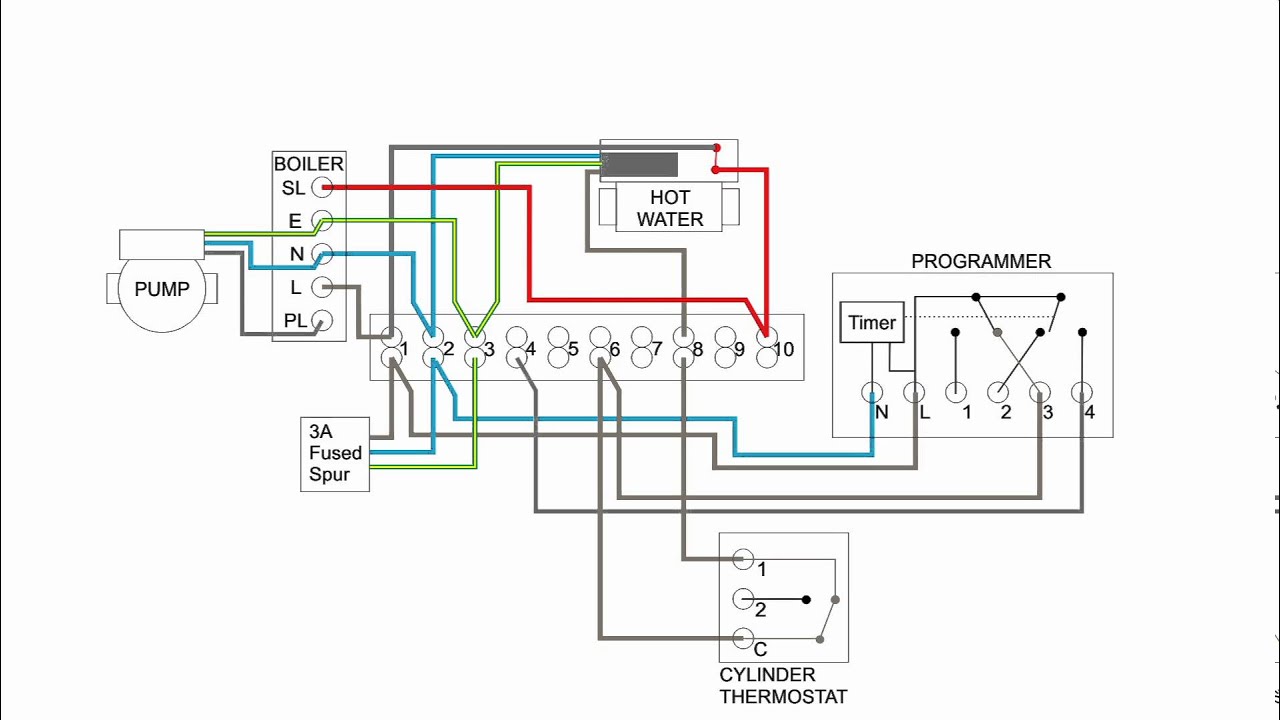
This scheme uses separate two-port valves, one for hot water and another for heating. It can be easily extended to include additional heating zones by adding an extra valve and room thermostat for each zone – this is typically called S Plan Plus.
This video covers the wiring and. S Plan wiring diagram with RF unit. C.
1. 2. E.
1 2 3 4 5 6 7 8 9 10 11 12 13 14 15 E. E.
How does a s plan system work basic central heating
E. E.
N. Programmer.
Model Nos. EP/SP Cylinder Thermostat.
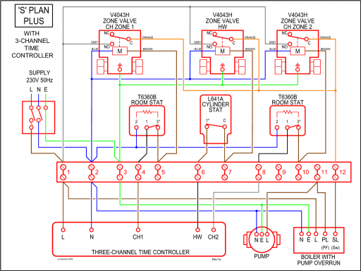
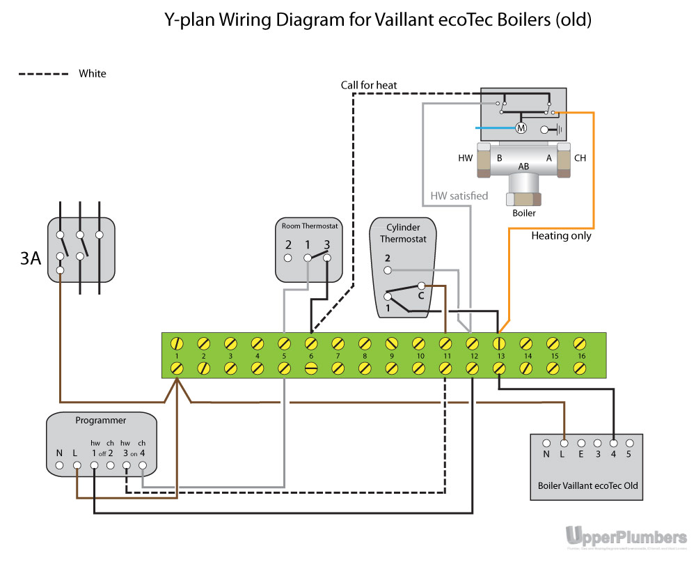
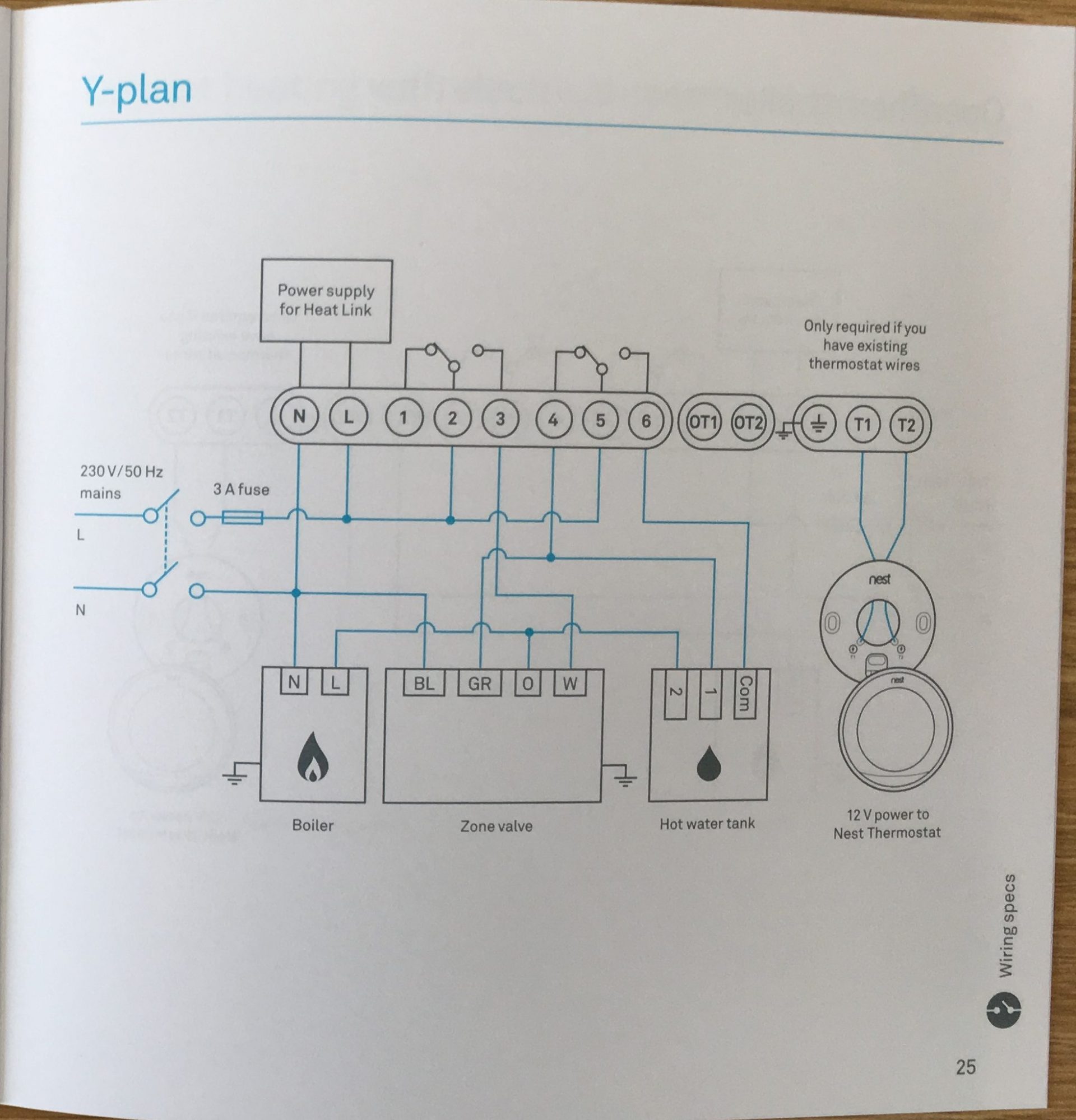
This article shows a typical S Plan wiring diagram and gives an overview of the electrical control wiring connections for a Sundial / Honeywell.Jul 07, · Simplified S-Plan and Y-Plan Wiring diagrams Discussion in ‘ Central Heating Systems ‘ started by Jamchiv01, Nov 20, Discuss Simplified S-Plan and Y-Plan Wiring diagrams in the Central Heating Systems area at schematron.org System Wiring Diagrams. Y Plan System Schematic. Showing flow from boiler, to Y Plan, or Mid Position Diverter Valve, and then onto heating or hot water circuit.
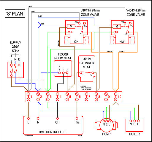
Y Plan Wiring. S Plan Schematic.
Wiring Diagram of S Plan Central Heating System
Showing flow from boiler, up to S Plan Valves, or Zone Valves, then onto heating and hot water circuit. S Plan Wiring.
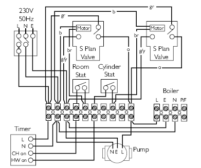
“Supplying and installing the latest in air conditioning technology’ schematron.org air conditioning Celsius Air Conditioning Ltd, I XNell Street, Heywood, Greater Manchester OLIO I NT. Sundial Y Plan satisfies the minimum standard requirements of the Building Regulations Part L1 when used in conjunction with radiator thermostats and an automatic bypass valve.
For systems in dwellings with a floor area greater than m², Sundial S Plan Plus must be used. UFH to S Plan Wiring Info.
Typically you’ll need to run 3 cores and earth from the S Plan wiring centre to the UFH wiring centre as per the diagram. I would recommend installing a 3 pole switch to this cable to make it easy to isolate the UFH from the rest of the system.| Drayton Controls : Heating controls, TRVs and thermostatsCentral Heating Wiring Diagrams