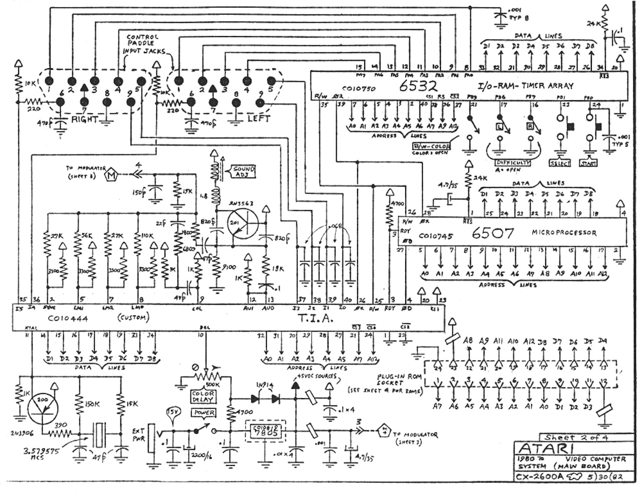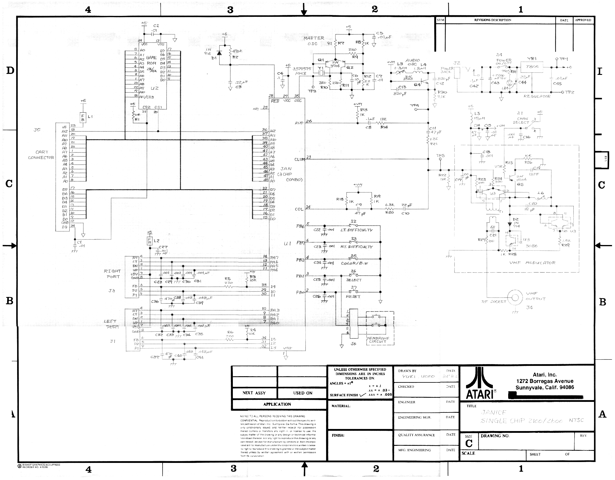
Atari believes that the information described in this manual is accurate and reliable, and much .
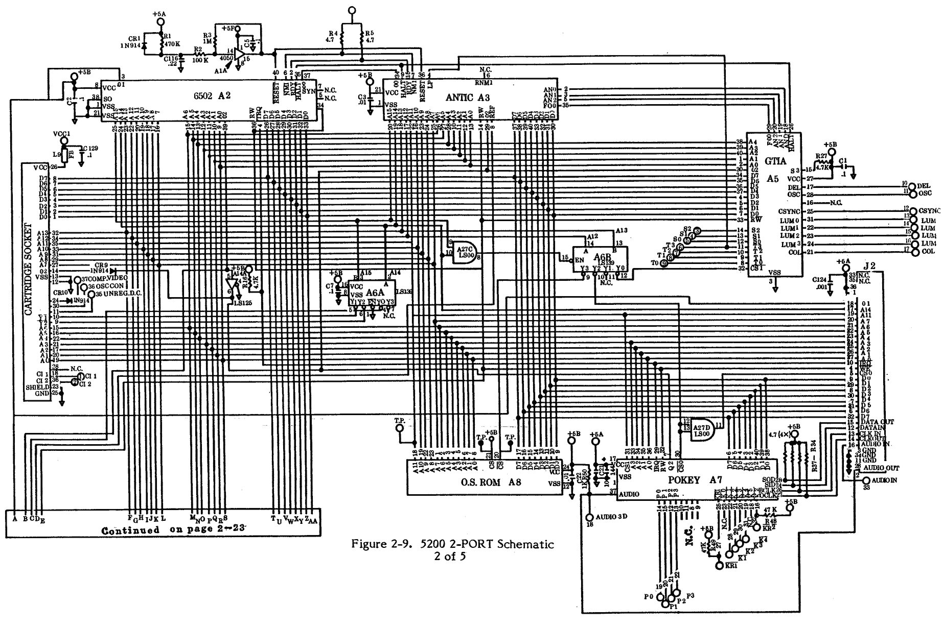
diagram of the functional flow of the VCS Model .. Extreme care should be taken when handling the integrated circuit chips (A, A20 1. Here are the schematics for the 6 switch and 4 switch systems.
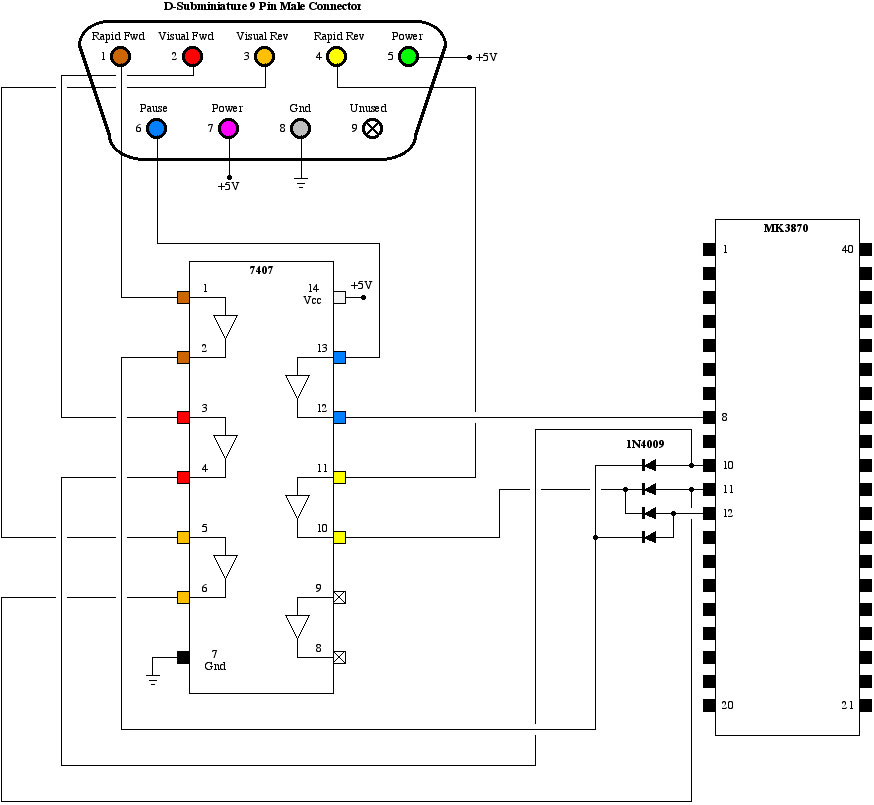
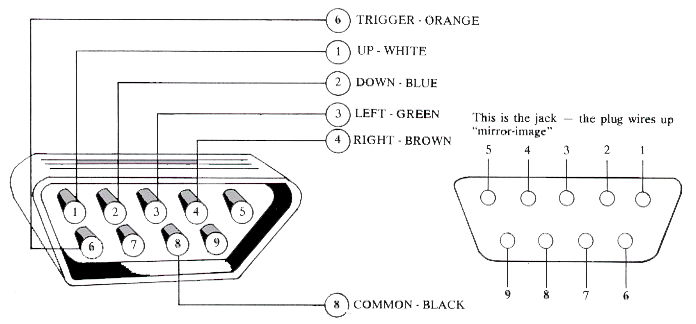
Pinout of Atari joystick and layout of 9 pin D-SUB female connector and 9 pin D-SUB male connector. Here are the schematics for the 6 switch and 4 switch systems.
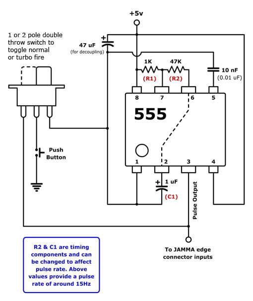
The most common joystick type in home computers have been Atari-style digital joysticks. All of the swiches are connected between ground and corresponding signal pin of the joystick connector. Atari , , XL, XL, XL, 65XE, XE and XE have the same connector and.Sep 08, · UAV Modification Wiring Schematic/Diagram for and A – posted in Atari Hi everyone, I didnt want to bother @Bryan, as he seems quite busy, but Im wondering if theres an actual drawn schematic for the UAV board installation on both light sixers () and the 4-switch woodgrain, Vader and Jr?.
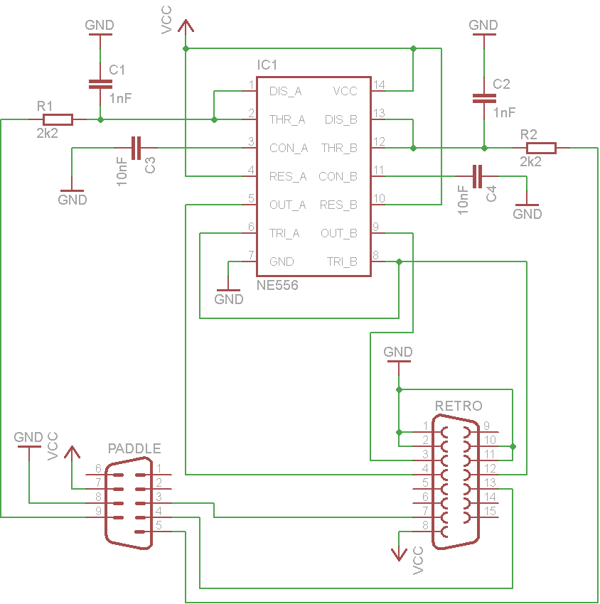
The article will guide you on how to use NES controller in Atari or ZX Spectrum using an Arduino. Read through the entire article to have a better idea.
Pole Position Game Wiring Interfaces ATARI INC a net SP 8th. voc SIC INPUT AUDIO 3VOC- RegulatorlAudio Il eøøv PCB Schematic Diagram q 3 8 7 5 4 9 87 eØv. Evinrude power pack wiring diagram.
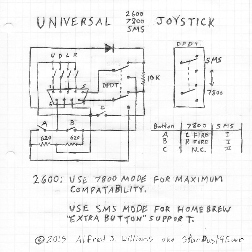
I’m looking for a FACTORY I’m looking for a FACTORY wiring diagram for a Evinrude Vindicator hp ESTLER. The factory manual pn is Here are the schematics for the 6 switch and 4 switch systems. Atari Game Controllers (Wiring Diagrams & Schematics) THE FOLLOWING PAGES CONTAIN DESCRIPTIONS, SCHEMATICS AND TEST PROCEDURES FOR THE FOUR GAME CONTROLLERS USED WITH THE ATARI VIDEO COMPUTER SYSTEM ().The Atari VCS Portables Site – “How To”Atari joystick pinout and wiring @ schematron.org
