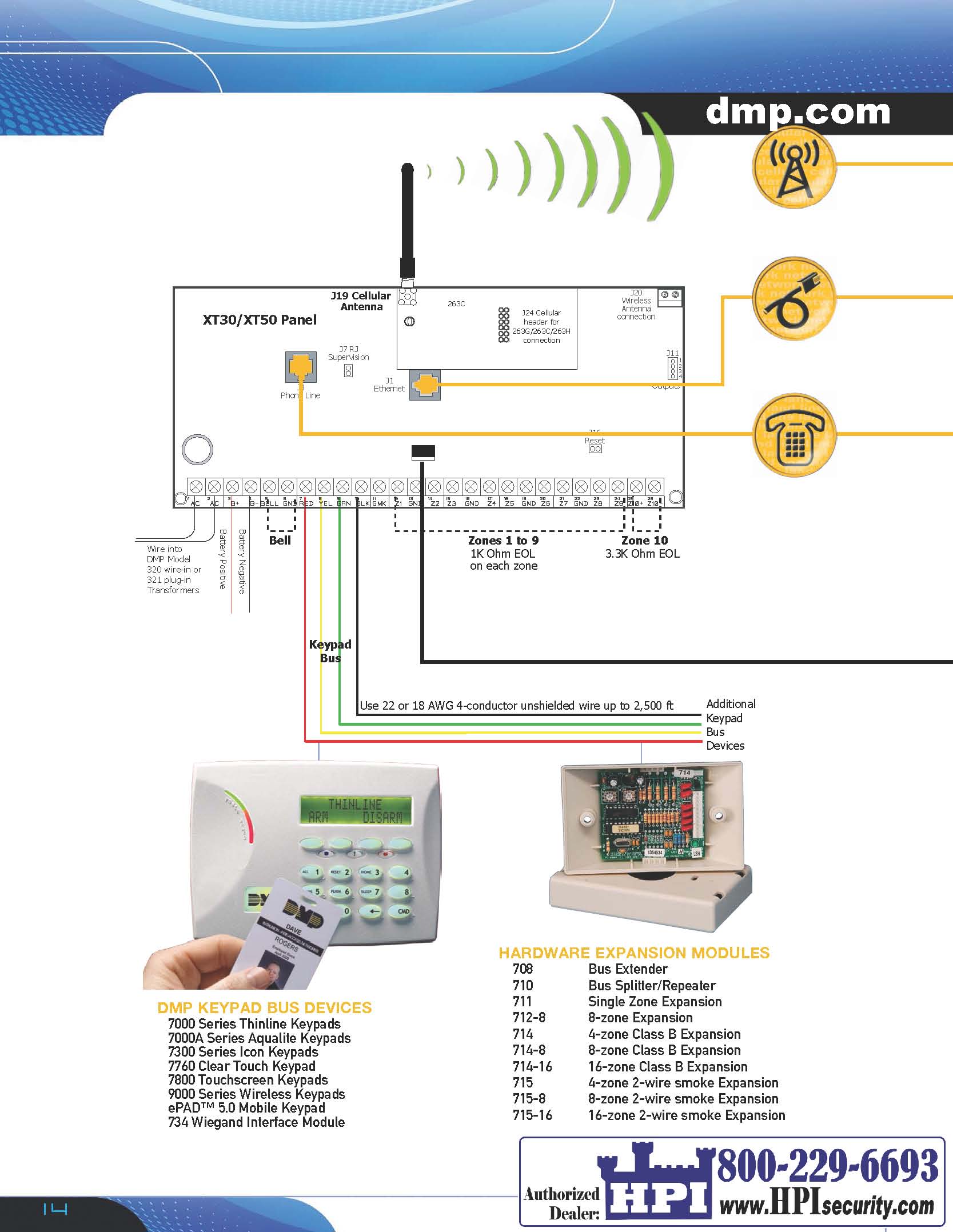
/ Zone Wiring These modules use a wire harness for wiring connections. . Zone Protection diagram in the XR/XR and XR/XR/XR MODEL XR, XRN, XRE SERIES.
CONTROL Information furnished by DMP is believed to be accurate and reliable. Wiring Diagrams. To Initiating Zone DMP Model Normal/Silence Switch 30mA @ 12 VDC WIRInG dIaGRaMs Smoke Alarm DMP Electronics Installation Manual.
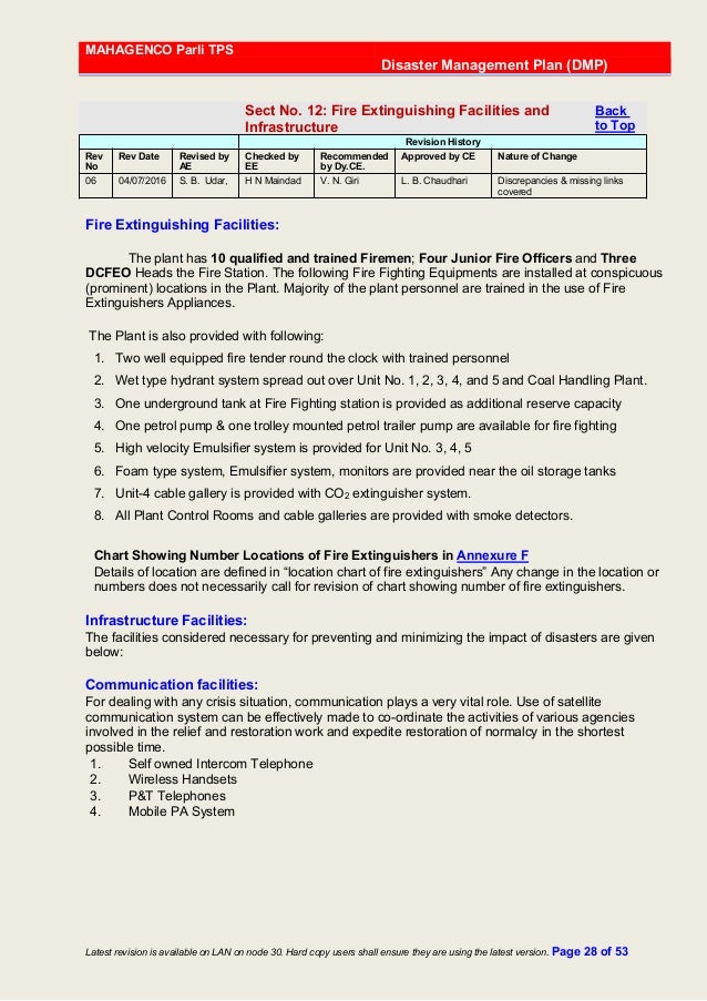
10 Wiring a Supplemental Power Supply. ______ ______ XR J4 Tamper header and Model Tamper Harness wiring diagram ______ ______ To.
DMP Electronics XR2500F Smoke Alarm User Manual
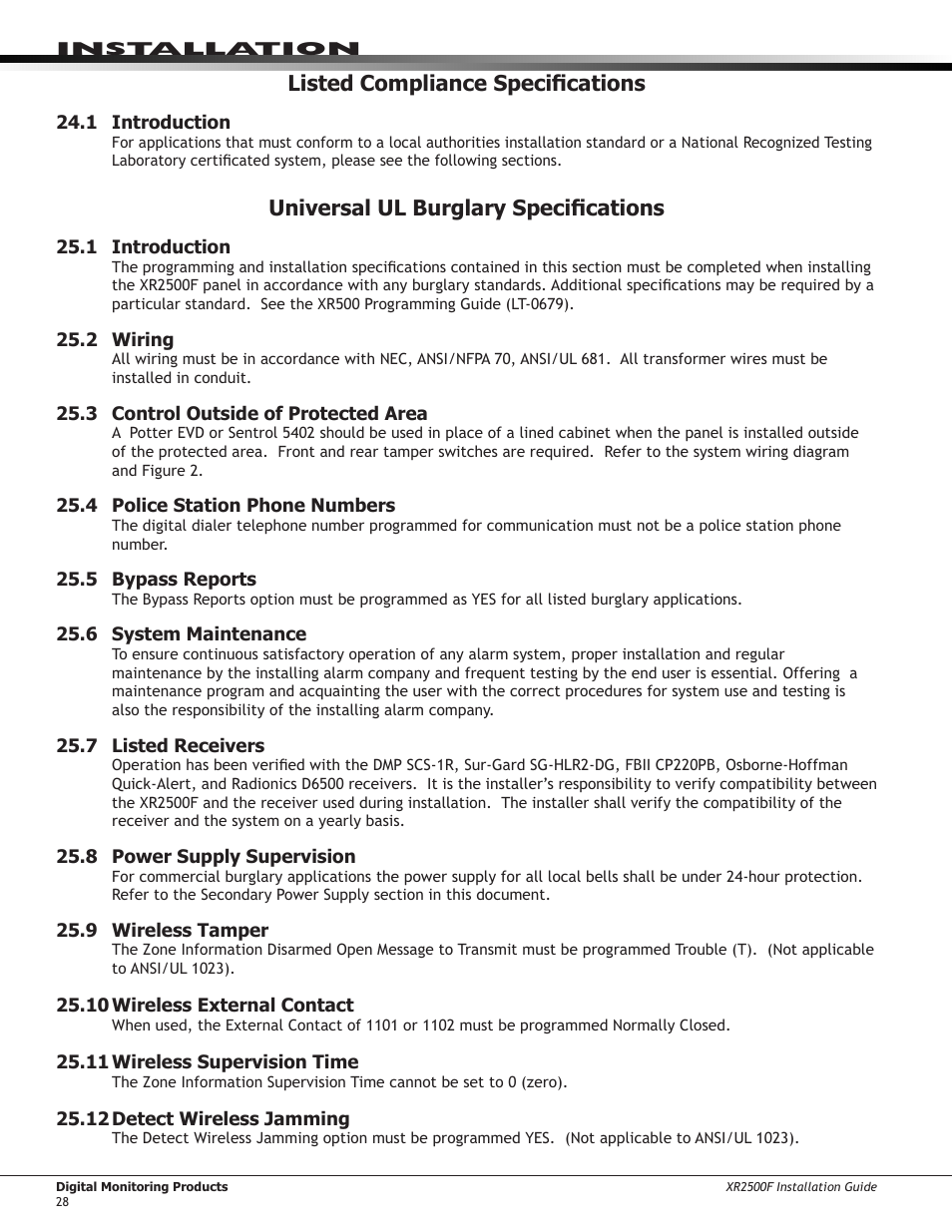
Laboratory certificated system, please see the Wiring Diagrams for The DMP XRFC Series system is made up of an alarm panel with a built-in communicator, an enclosure, battery, wiring. See the XR Series Installation Guide for a.DMP has released its latest new panels, the XR/ Series.
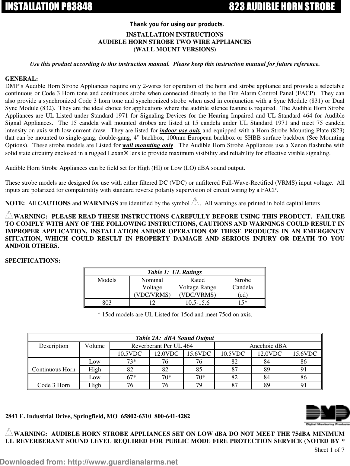
Their bit processors operate at 20 times the speed of the DMP XR panel; with 10/ Ethernet auto-sensing that always ensures the fastest-possible network connection. Use the DMP A Dual Phone Line Module when connecting the panel to two separate phone lines in fire or burglary applications. Page 8: Wiring Diagram. SYSTEM COMPONENTS System Components Wiring Diagram The XR/XR Series diagram below shows some of the accessory modules you can connect for use in various applications.
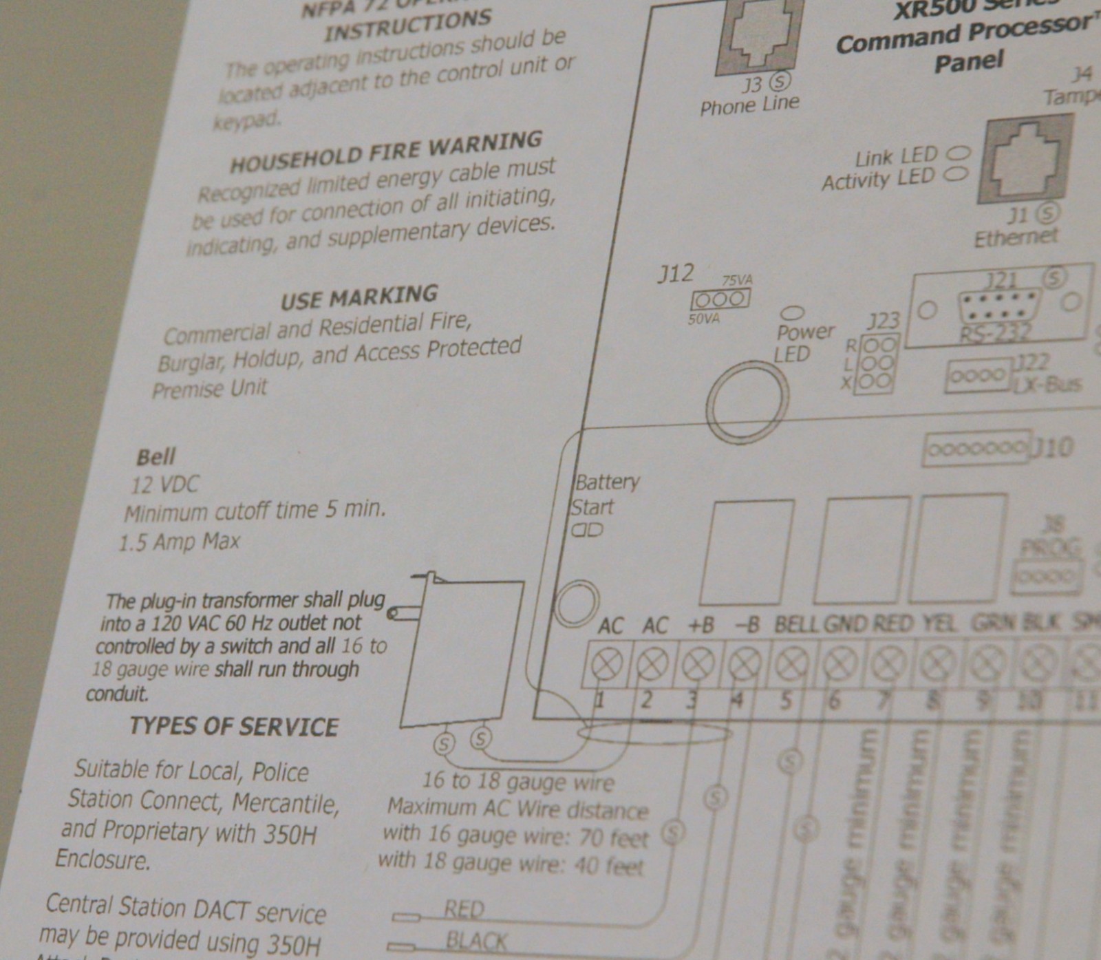
The DMP XR Command Processor is a versatile 12 VDC, combined burglary and fire communicator panel with battery backup. The XR provides eight on .
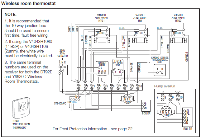
Information furnished by DMP is believed to be accurate and reliable. This information is subject to change without notice.

XR Series Installation Guide Digital Monitoring Products. Model XR Series Wiring Diagram Refer to XR Series Installation Guide (LT) for a complete description of wiring connections. Refer to XR Series Programming Guide (LT) for complete programming instructions.Page 51 of DMP Electronics Smoke Alarm XRF User Guide | schematron.orgXR Wiring Diagram | schematron.org
