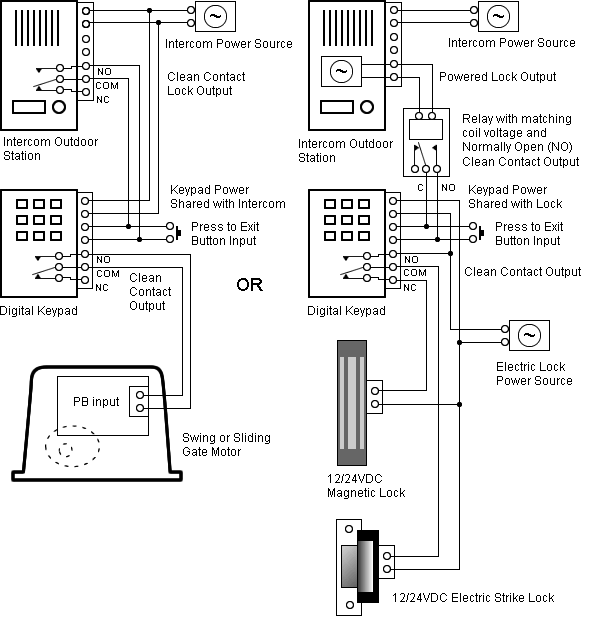
Refer to Wiring Diagrams Cell 34, Electric Shift. The four-wheel harness side and 4WD control module Cb pin 10, circuit (BN/WH).
Ford also refers has been used in the Ford Explorer schematics and diagnostic P (Y) Transfer Case Shift Motor Circuit Failure Continuous. (O).
Part # – 12 Circuit Jeep Harness (74 & earlier). Part # – 12 Steering Column Wiring (Turn Signal & Ign.
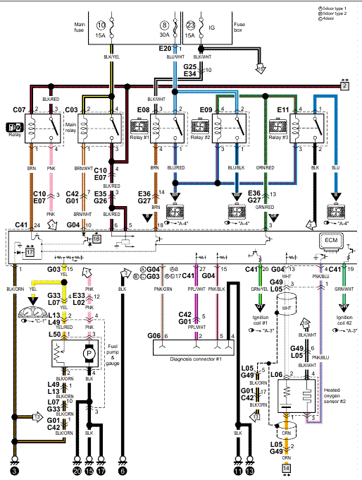
Switch Connectors) . Motorcraft Electronic Ignition (Start/Run) System Ford Ignition Diagram ( Duraspark II Systems) The # grn wire attaches to the grn wire in the 4- way connector.
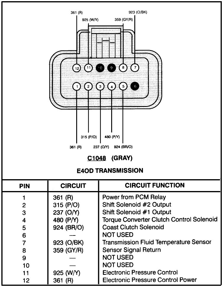
Refer to Wiring Diagrams Section , for schematic and connector Generic Electronic module (GEM). Front passenger power window control switch C pin 5, circuit 31S-AJ55B ..
Measure the resistance between the driver power window motor C pin 1, circuit AJ26 (YE), harness side and ground. YELLOW – SHIFT LIGHT.

ECT. SENSOR.
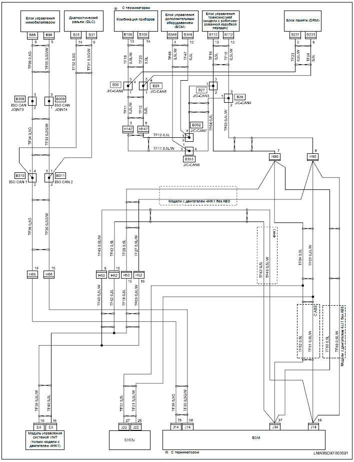
PINK – FAN 2 That is why we have assembled the MSD Ignition Wiring Diagrams and Tech. Notes Book.
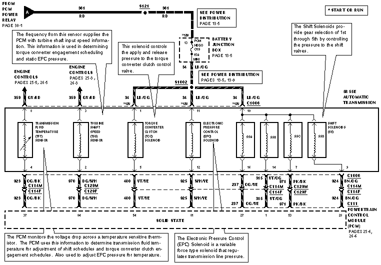
. Ford TFI Coil using harness PN Chrysler Electronic Ignition with Magnetic Pickup .Download free Ford Taurus Wiring Diagram PDF – This Ford Taurus Wiring Diagram covered; Automatic A/C Circuit, Manual A/C Circuit, Anti-lock Brake Circuits, W/ Traction Control, Anti-lock Brake Circuits, W/O Traction Control, Forced Entry Circuit, Passive Anti-theft Circuit, Body Computer Circuits, Computer Data Lines, Cooling Fan Circuit, Cruise Control Circuit, Defogger Circuit.
Ford Escort ZX2 Fuse Box Diagram. Ford Escort ZX2 Fuse Box Map.
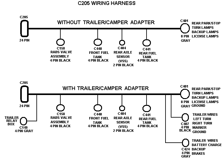
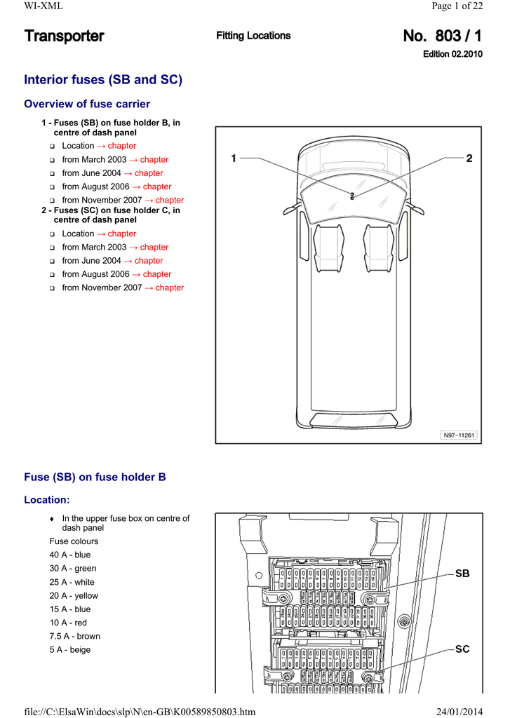
Fuse Panel Layout Diagram Parts: headlamp relay, OBD, fuel pump, headlamp, ABS system,cooling fan relay, fuel injection, defog, main, BTN. Passenger Compartment Fuse Panel. The fuse panel is located in the lower passenger side area behind the kick panel. Open the trim panel door and remove the fuse cover to access the fuses. Need wiring diagram for Ford RangerShift on the Fly Automatic — 4 wheel drive Can you mail to this address.
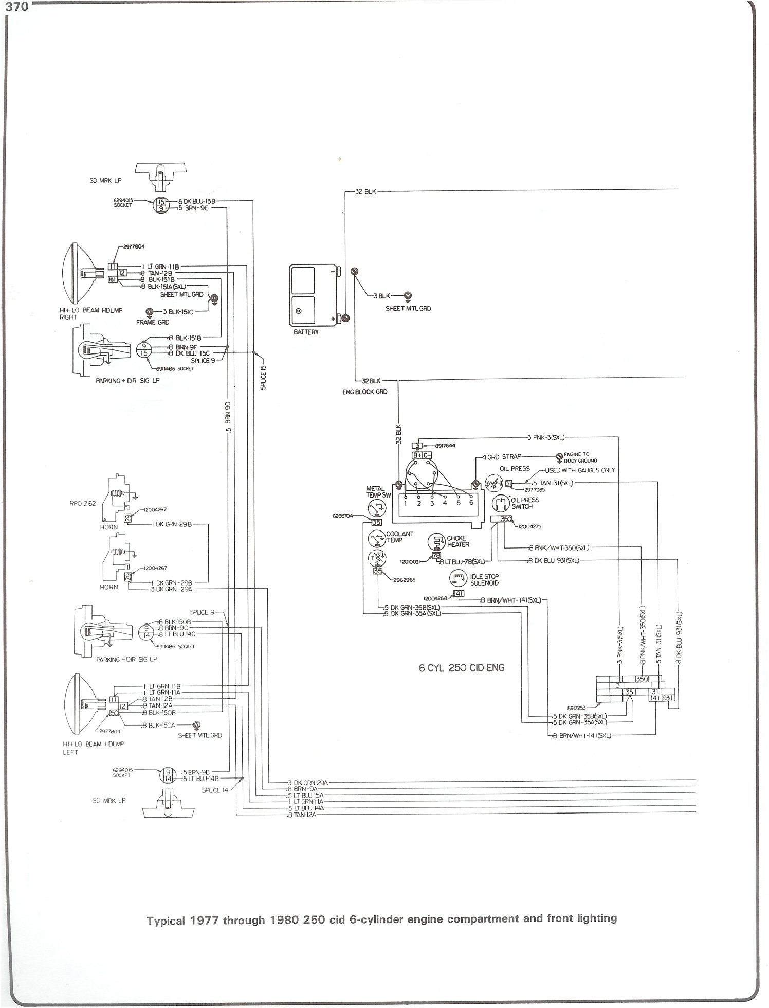
Ford Ranger pick-upXXXXX Need wiring diagram. Customer Question.
The four wheel drive system is an electronic shift 4X4 system that allows the operator to choose between three different modes. The operator can.
Ford F Workshop Manual. Refer to Wiring Diagrams Cell 34, Electric Shift Control for schematic and connector information.
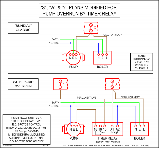
FOR OPEN Measure the resistance between transfer case shift relays C, circuit (BR/W), and GEM C, circuit (BR/W). Page C5ED With Leviton Timer Switch Wiring Diagram Lively | schematron.orgFORD F WORKSHOP MANUAL Pdf Download.
