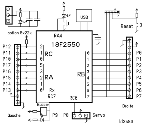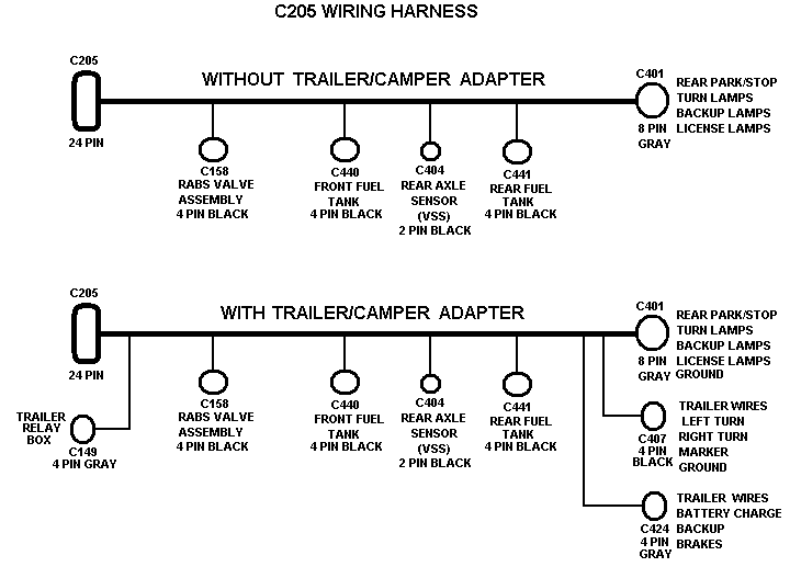
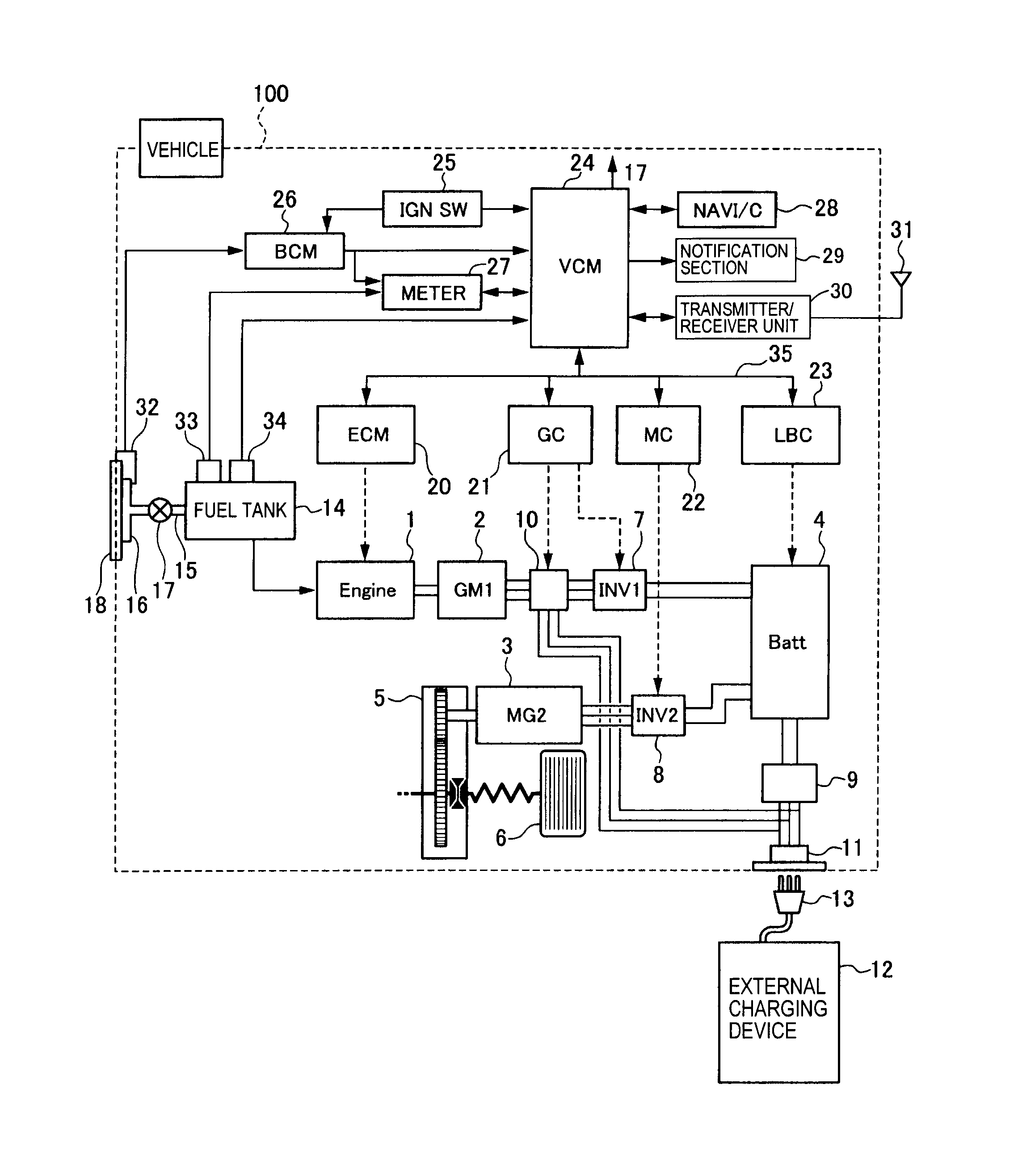
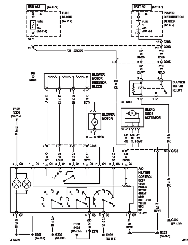
23 Maschinenfabrik Reinhausen /00 EN TAPCON® 3 Table of contents Storage Wire the device according to the connection diagram.
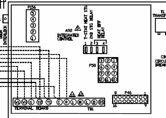
Before commissioning, the TAPCON® connection diagrams should be checked. The diagram below shows the interfaces available and the operating and.
TAPCON® Figure 4: Operating controls. RAISE key: Sends control command for raise tap-change to the motor-drive unit in manual mode. TAPCON® Operating Instructions.
/03 EN. Three-winding TAPCON® Table of contents. 1.
Introduction. .. Wiring device.
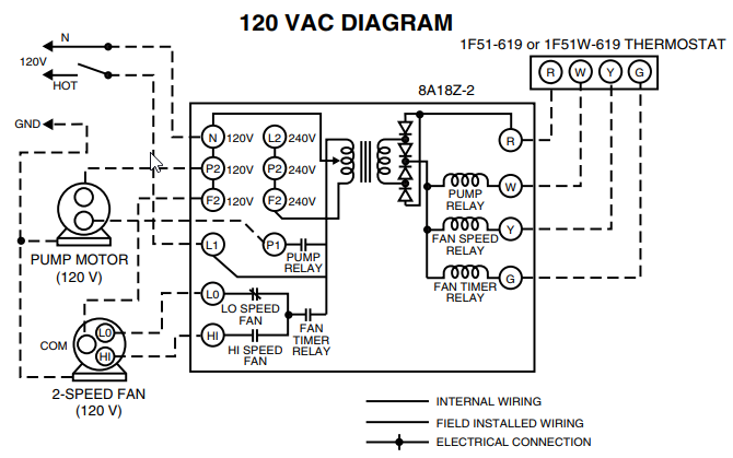
In manual mode, you can perform manual tap-change operations to increase TAPCON® . the connection diagram provided for the configuration.Get the job done right the first every time with the Tapcon Pro Installation Kit. The Tapcon Pro Installation Kit is a power tool attachment that drives Tapcon anchors and is compatible with all impact drivers, hammer drills and rotary hammer drills.
Use the Tapcon Pro Installation Kit to make any /5(23). TAPCON® – PROVEN TECHNOLOGY, MAXIMUM INdIVIdUALITY.
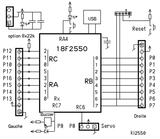
With the TAPCON® , there are no limits to your individual voltage regulation requirements. 5 Extending beyond the function of the TAPCON ® , our professional TAPCON device offers virtually unlimited possibilities.
The firmware of the TAPCON® is adapted specifically to your needs. Tapcon Screw Anchor – Technical Data Ultimate Tension and Shear Values (Lbs/kN) in Concrete Tapcon® Anchors PERFORMANCE TABLE ANCHOR DIA.
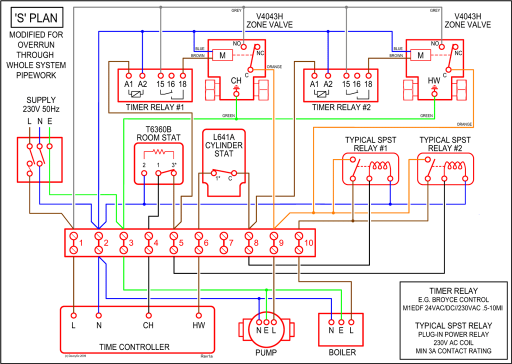
In. (mm) MIN. TAPCON® Circulating Current Analog Paralleling Paralleling Assistant XPA-I • Easy adaption for paralleling via • CAN bus to Digital Voltage • Controllers of the TAPCON® family • Simplified installations less wiring time and reduced failures • Cost savings CAN bus Analog August Page Search among more than user manuals and view them online schematron.orgINSIGHT – TAPCON® – now with IECVoltage Regulator TAPCON® | schematron.org
