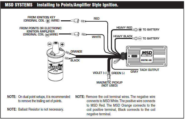
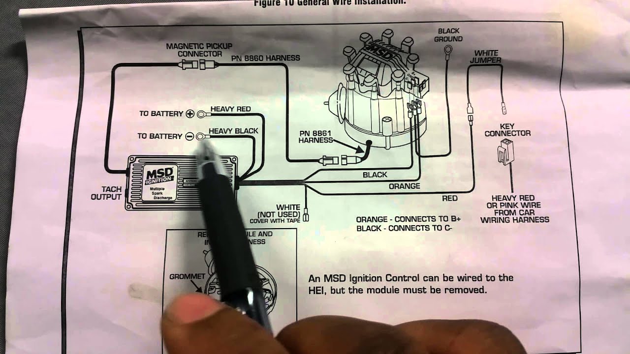
the ignition including trigger signal, low voltage and high voltage. 1 – Harness, PN 2 – Violet Jumpers Note: Solid Core spark plug wires cannot be used with an MSD Ignition.
done with the Cylinder Select dial and is explained on page 5. .
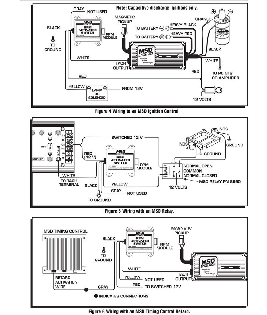
Points circuit (the White wire) and a Magnetic Pickup circuit (the Green . COM • (9 1 5) 8 5 7 – 5 2 0 0 • F A X (9 1 5) 8 5 7 – 3 3 4 4 Note: Solid Core spark plug wires cannot be used with an MSD Ignition. The MSD Ignition features a Gray Tach Output wire that provides a trigger signal for tachometers, a .
The Digital 6A and 6AL use a main wiring harness that connects to the ignition . the tach’s trigger wire directly to the tach output of the Ignition.
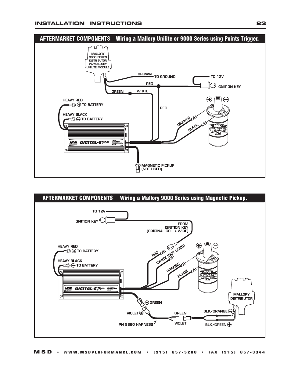
The wiring diagrams show both installations. Wiring with a Magnetic Pickup Distributor and a Voltage Triggered Tach. COM • (9 1 5) 8 5 7 – 5 2 0 0 • F A X (9 1 5) 8 5 7 – 3 3 4 4 Wiring a Current Triggered Tach to Points/Amplifier or Magnetic Pickup.
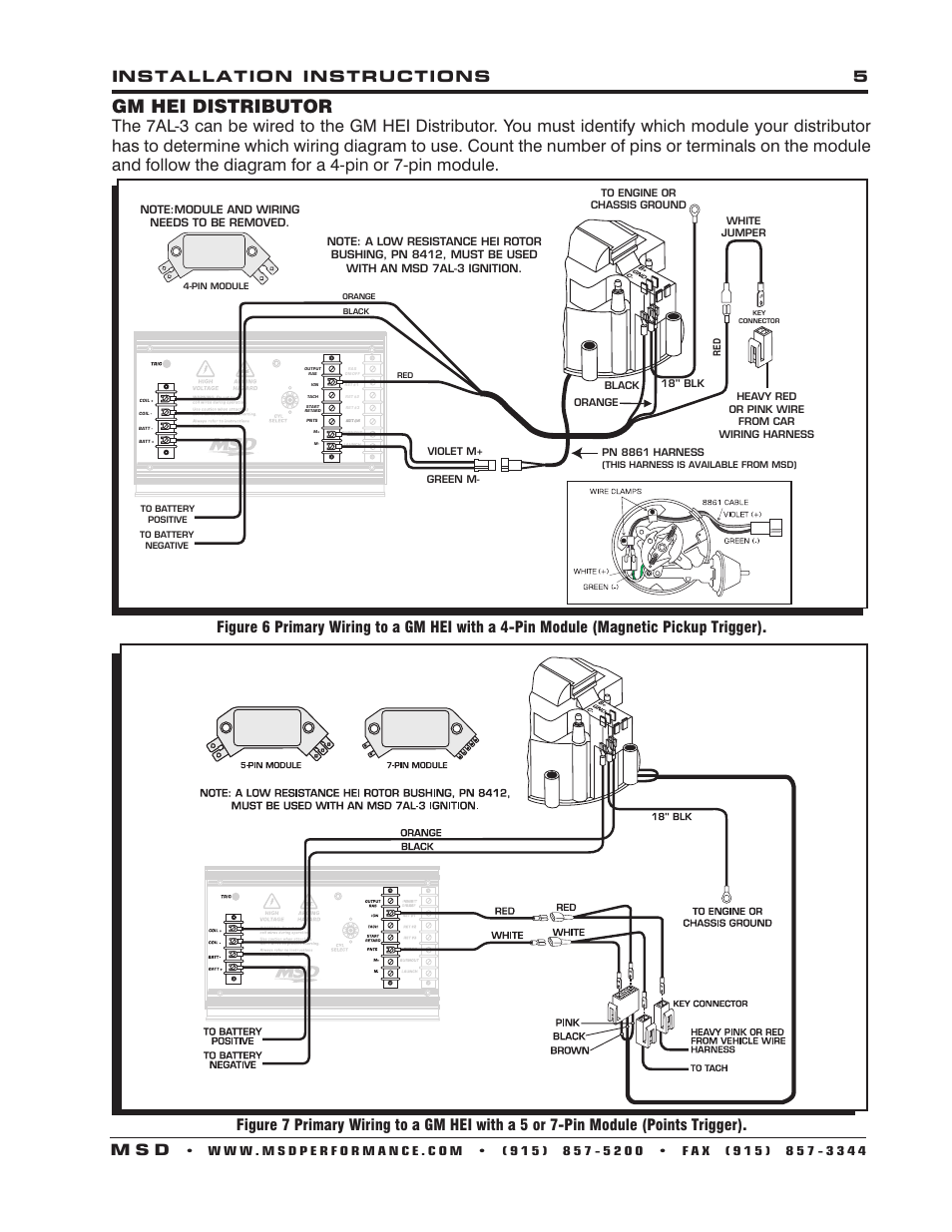
to get Book file PDF Msd Wiring Diagram Point Trigger. MSD Tech determine which wiring diagram to use Points Trigger Figure 5 Primary.
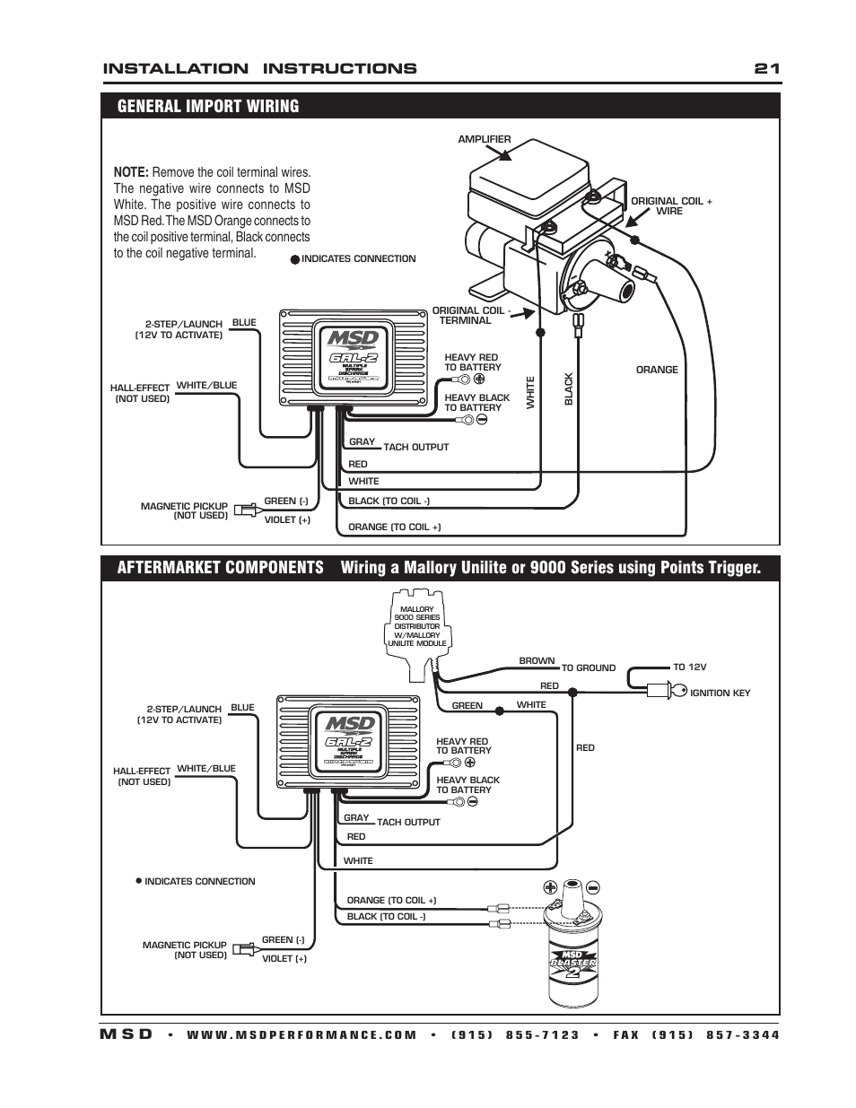
schematron.org • () • FAX () ® The Street Fire Ignition features a Tach Output wire that provides a trigger signal for tachometers, a shift light or other . This wire is used to connect to the points or electronic ignition amplifier output. GM IGNITIONS Wiring with an MSD Wiring Harness.Msd Distributor Wiring Diagram (Oct 30, ) – Knowledge about msd distributor wiring diagram has been submitted by Maria Rodriquez and tagged in this category.
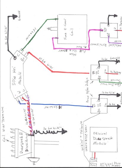
Sometimes, we might have to slightly alter the layout, color, or even accessories. MSD 6 Series to Chrysler electronic ignition using magnetic pickup; MSD 6 Series to Chrysler (late model) with 2 pin coil; MSD 6 Series to Ford Duraspark using white trigger wire; MSD 6 Series to Ford Duraspark using magnetic pickup; MSD 6 Series to Ford TFI coil (with harness) MSD 6 Series to Ford TFI coil (without harness).
gered from coil +) and are using the White wire of the MSD as a trigger, a Chrysler Dual Ballast Resistor (used from ‘’76) may be used to cure the tachometer. The diagram below shows the correct wiring.
Tachometer Compatibility List AFTERMARKET TACHOMETER WHITE WIRE TRIGGER MAGNETIC TRIGGER CONNECTOR AUTOGAGE /5(2). Points: If you are using a Points style distributor or electronic amplifier, only the “Points” terminal will be used.
Connect the supplied WHITE jumper wire from the points output in the distributor to the “Points” terminal (Figure 1). Magnetic Pickup: If you are using an MSD Distributor or Crank Trigger, only the Magnetic Pickup.
Oct 01, · MSD will work with points too. Go electronic and the points will not wear, as they only act as a trigger and carry hardly any current.
You don’t need a condenser, and only need to check the dwell and timing once a year if that, in case the rubbing block has worn a bit.Msd Wiring Diagram | Best Books ResourcesReworking a Stock Distributor to Trigger MSD Ignition Systems Part 4 – RacingJunk News