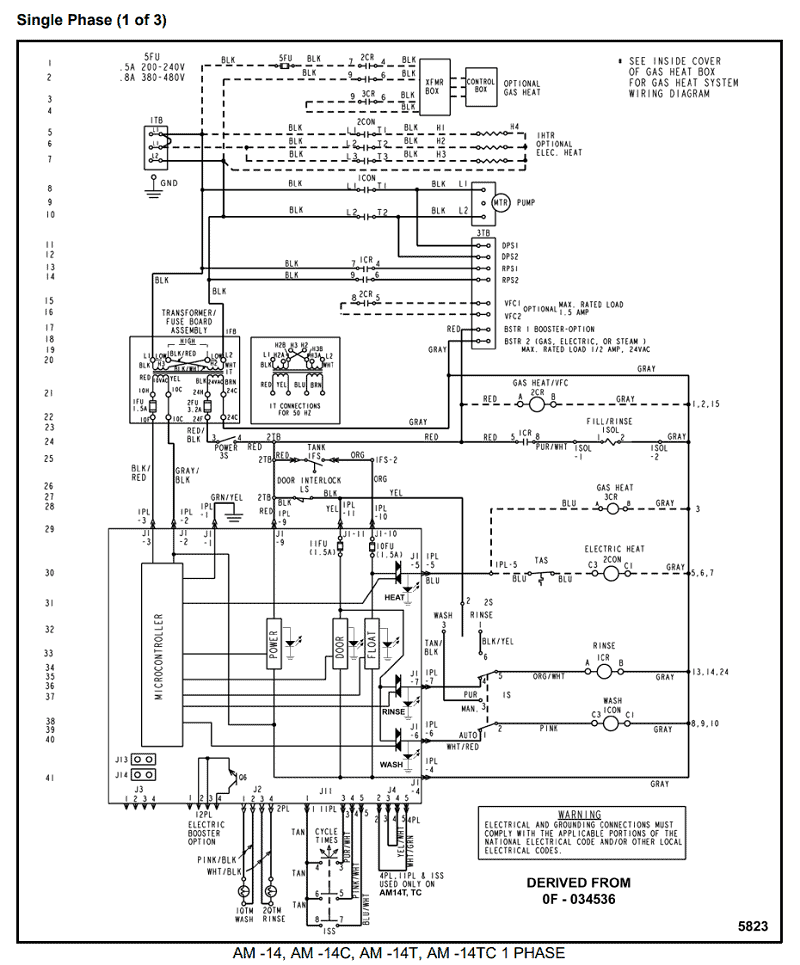
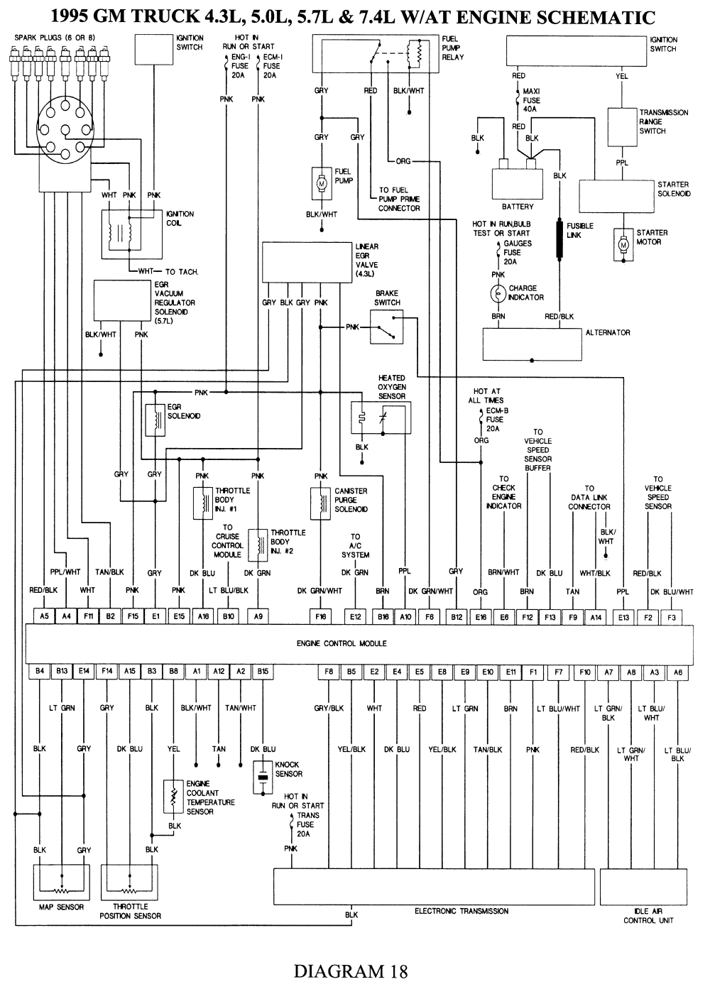
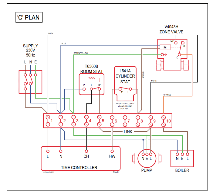
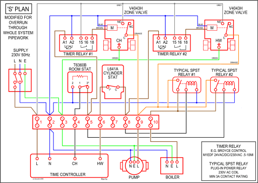
I need a schematic diagram for a York Furnace.
– 0f0a96db7c Depending on the type of blower motor you have this diagram may not. Every few years York updates their furnace circuit board to accomodate both the newer AND the older furnaces.
This is the only York Luxaire Coleman Furnace Control Circuit Board Estimated by eBay FAST ‘N FREE Frequently Bought Together1/2 4 ton York air conditioner & Heat P. WIRING DIAGRAM – DOWNFLOW.
1. Spray or aerosol cans, rags, brooms, dust mops, vacuum cleaners or other cleaning tools.
2. Soap powders, bleaches, waxes or ..
Air Source from Outdoors -. 1.

mostat to the terminal board on the low-voltage transformer. Connect IGNITION CONTROL (P/N ).
controls, control system parts, electrical parts that have been wet .. wire that is connected to the cooling terminal on the control board.
. with UPG Source 1 Parts.
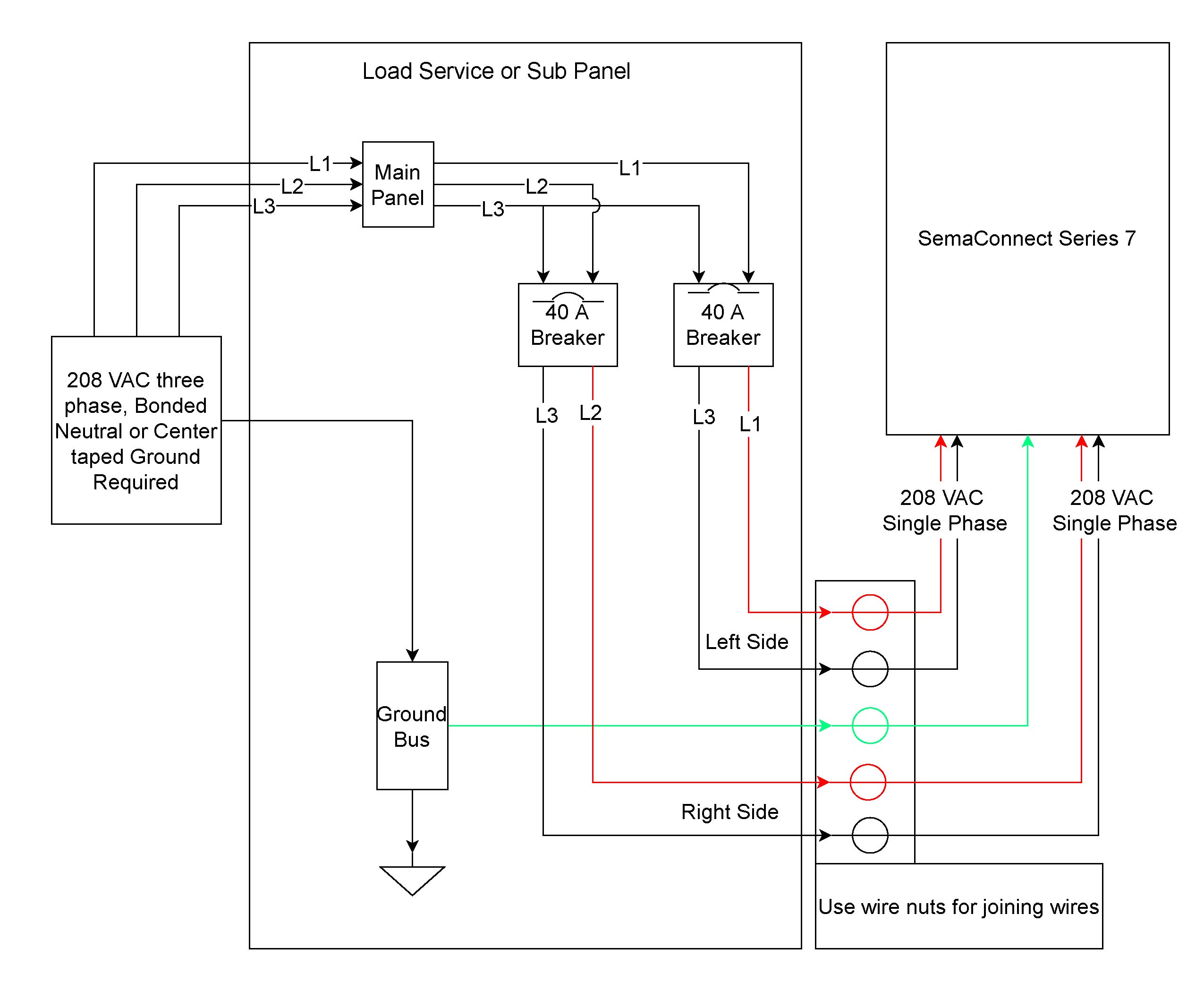
IGNITION CONTROL (P/N ) . FIGURE 9: Wiring Diagram. Every few years York updates their furnace circuit board to accomodate both the newer AND the older furnaces.
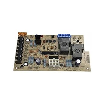
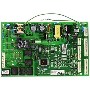
This is the only York Luxaire Coleman Furnace Control Circuit Board Estimated by eBay FAST ‘N FREE Frequently Bought Together1/2 4 ton York air conditioner & Heat P.ICM offers low cost, form, fit and functional furnace control board replacement for many popular OEM models. Our furnace control boards come standard with many safety features including percent gas shutoff in case of ignition failure.
1. Ignition control P/N or 2.

Hole template 3. Installation Instruction P/N Connect the control wiring as shown in the diagram below. 1.
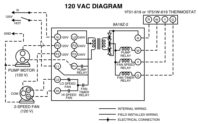
Connect the low voltage wiring from the wall ther-mostat to the terminal strip on the control board of Furnace #1. 2. Connect a wire from the TWIN terminal of Furnace.
Coleman YORK A Control Circuit Board SOURCE 1 $ York Coleman P Furnace Control Circuit Board SOURCE1 A $ Honeywell LENNOX 02 Furnace Control Circuit Board A $ Furnace Control Circuit Board 50A65 DP01 White Rodgers Trane. This is a Brand New Upgraded York/Luxaire/Coleman Furnace Control Circuit Board. This Board replaces all control boards in furnaces where the Model # begins with one of the following prefixes: GY9 GF9 GM9 P1UK PAKU P2MP P2MPV P9MP P2UR PBLU P2LN P2DP P3UR PCLU P1CX PACR XED P(12)CD P(AB)ND XND DGD GDD P3HU P3GEB GUD DGU PCUH P1DU FL8 P3UR G9T FG9 5/5.
(Every few years York updates their furnace circuit board to accomodate both the newer AND the older furnaces. This is the only board you can now buy for these furnaces.).
The York/Luxaire/Coleman Par.Furnace Electronic Control Board | Part Number | Sears PartsDirectYork Control Board | eBay