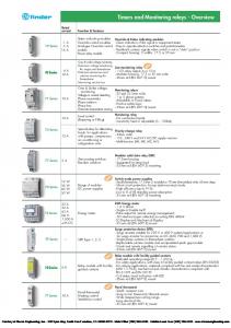
General Purpose Type AA Relays. . C = LCD. Front Dimension.
How to Connect a Three-Phase Monitor Relay
48 = 48 x 48 mm. Power. = Battery-Powered. = ac Power.
Wiring by mouse click – circuit diagram and parameter input
= dc Power 1PDT Spring-Cage Connection. No. 6A .. 50/ 50/ 60/ A. B. C.
/ 60/ 50/ 50/ D. E.
H. 6. 24 .. Sequential Function Chart. Timers. 8. Benefit: Offers installation & application flexibility when using different size wires.

.. Frame B – C contactors with 1NC built-in auxiliary are mirror contacts (XTCE. H. []. []. []. D1.
[]. []. M6.
Dia. W D3PR5A. S.
ASE Certification Practice Tests
Relay 10 Amps 24V AC 2 Pole. 24V AC. D3PR5T. D1 Series General Purpose Relay Electrical Schematic.
Pluggable / 60/ C. / 60/ D. 50/ E. 50/ H. 6. Control Relays and Timers Relay Products D1 Series General Purpose Relay . 4 mA 3 Switching level 1 signal (“H”) >0.
surge protection Polarity protection. com V7-T 10 20 30 40 50 60 3 Ambient Temperature (°C) 3 Electrical Schematic 3 Pluggable Power D3PR5A D3PR5A1 3 Vac DPDT C-Bus Eight and Twelve Channel Voltage Free Relay C-Bus 8 and 12 Channel Voltage Free Relay Installation Instructions .. The diagram opposite shows.WIRING DIAGRAM Optional 4-Speed!
How to Connect a Single Pole Double Throw (SPDT) Relay in a Circuit
W Amps To change blower speed on units without a relay box installed refer to installation instructions Refer to furnace and/or relay box installation instructions for thermostat connections. If any wire in5 this unit is to be replaced it must be replaced with C thermoplastic copper wire of theR.
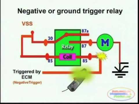
Switches, Relays and Wiring Diagrams 2
Your line note will last for the lifetime of the order schematron.orgt A Quote · Ask A Question · LED Lighting · Cabinet AccessoriesAll products: Connectors & Cable, Electromechanical, Passives and more. Thermostatic Wiring Principles by Bob Scaringe Ph.D., P.E.
Carrier 24ANB7 Wiring Diagram
to bring the C wire out to the thermostat in anticipation of a future installation of a thermostat that requires power. For systems that do not have access to the C wire, a wiring diagrams you may need to . Low Voltage Wiring Diagram: Heat Pump With Optional Economizer Factory installed jumper (on applicable models). B l a ck L E W3 R MIS B Low Voltage Wiring Diagram O/B Economizer F O1 Y1 W1/E RT Y1 B l a ck circuit if emergency shutdown required. O r ange A YO/D W1 Remove jumper and connect to N.C fire alarm 1 E Pu r p le Wiring Harness 1.
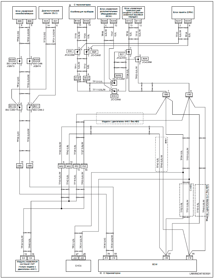
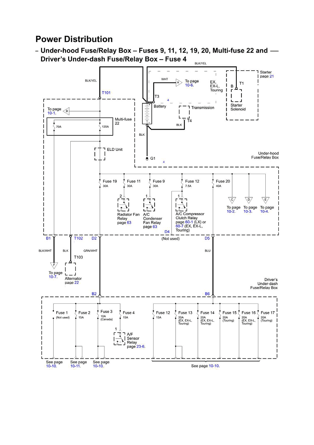
Using the Electrical Wiring Diagram Body Electrical Diagnosis – Course L 5 Table of Contents The Table of Contents is found on the title page of the EWD.
11 Pin Relay Connections – Working – Wiring And Base Wiring (Urdu/Hindi)
A second table of contents for just the System Circuit Diagrams is found at the beginning of Section I (Section H starting with MY).A/C Clutch Relay Function and TroubleshootingCARRIER 24ANB7 WIRING DIAGRAM Pdf Download.