Wiring Diagrams · Calculating BTUs · Brewery Wiring The MYPIN TA4 PID is one of the better controllers from China.
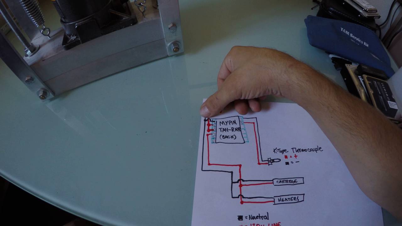
The PID is easy to use and easier to. So below are pictures of my wiring diagram PID settings and PID instructions ..
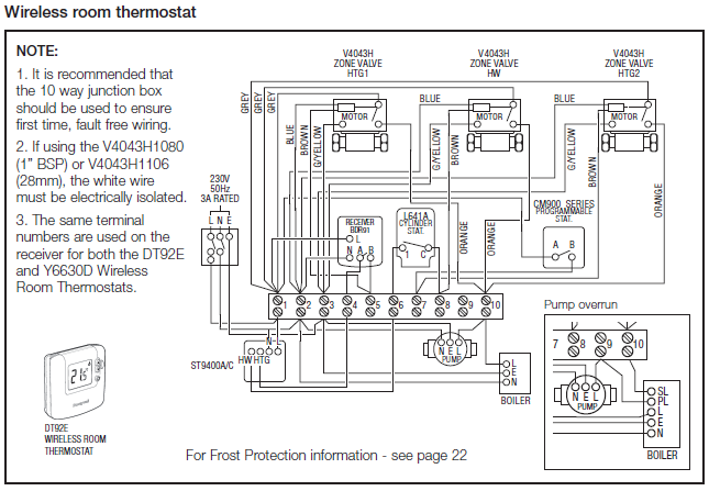
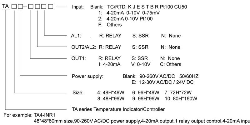
I hope I’m wrong, but isn’t it the mypin ta4 SNR that you need?. Before I set my house on fire, I wanted to verify things look good to accomplish the following: 1.

The single pole three switch receptacle is the. So below are pictures of my wiring diagram PID settings and PID instructions ..
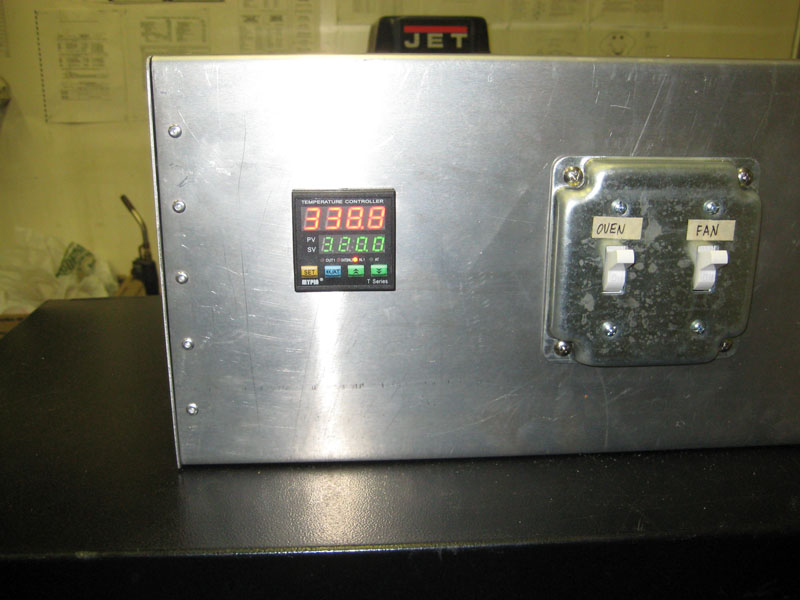
I hope I’m wrong, but isn’t it the mypin ta4 SNR that you need?. I bought a Mypin TA4 off eBay to save some $$.
I also bought a Rtd (three wire) probe from Auberins. I can’t seem to figure out how to . Would be easier to debug if you had a schematic/picture.
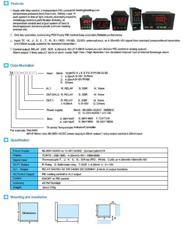
Describing electrical circuits.Check all the connection and wiring if it is all correct. Specially pay attention to the power supply terminals and signal input ternimals. Check if the input signal is conformity with the selected symbol.
For TC input, please use the relative compensation cable. For RTD input, please use low impedence cable. The 3 wires should at the same length.
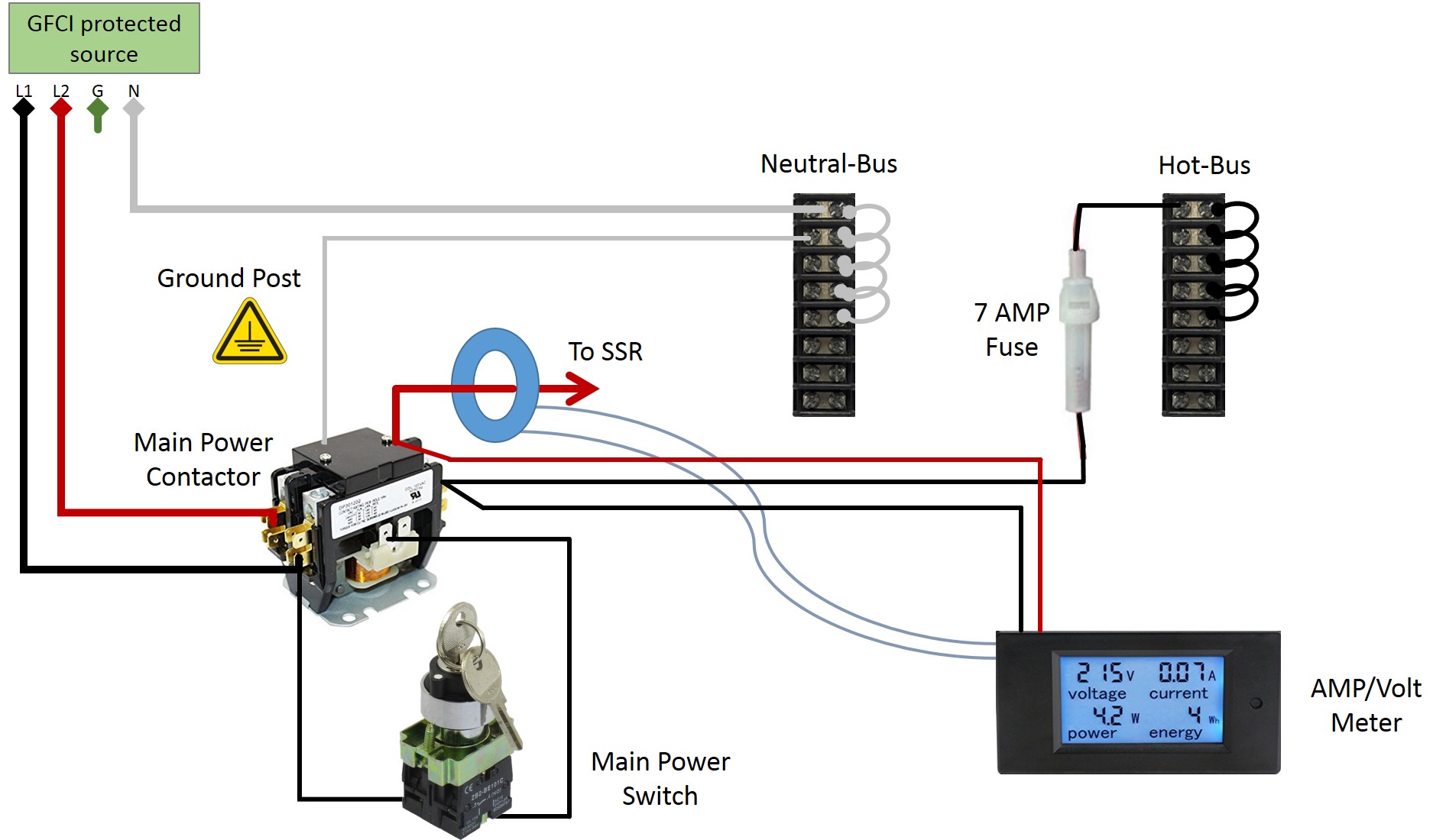
The core of the system is the myPin TA4 controller to the Futek SSR (wiring diagram here). I have them wired in the same configuration with the same thermocouple.
However, the instructions that came with the TA4 are a little confusing. Here is a scan of the manual.
I am not sure where to ask this question. I have a ‘MYPin TA7-SNR’ Temperature PID contoller.
I also have a PT Temperature Sensor. I have read the instructions that have come with the PID and I thought I had the sensor wires connected correctly, but it does not read a temperature.
May 23, · PID wiring help; If this is your first visit, I disconnected it from the pid and the pot will not come on. The pid is a TA4-snr.
, PM # Frozone. View Profile View Forum Posts Visit Homepage I will look on the diagram on the side of it to see if it elaborates which TA04 I have.
I only paid like $10 for the ssr with a. Typical Wiring Diagram Wiring & Installation Diagram for SSR-2 Solid State Relay Neutral Brass Term. SSR-2 (Top View) Sensor Switch SW.
LOAD LOAD Hot VAC Operating & Load Voltage Range Voltage Loss Sensor Current, Max. Allowable Resistance in Sensor Circuit to Turn “ON” (Max.).Need help understanding the MyPin TA4 temperature controller. : AskElectronicsPID wiring help
