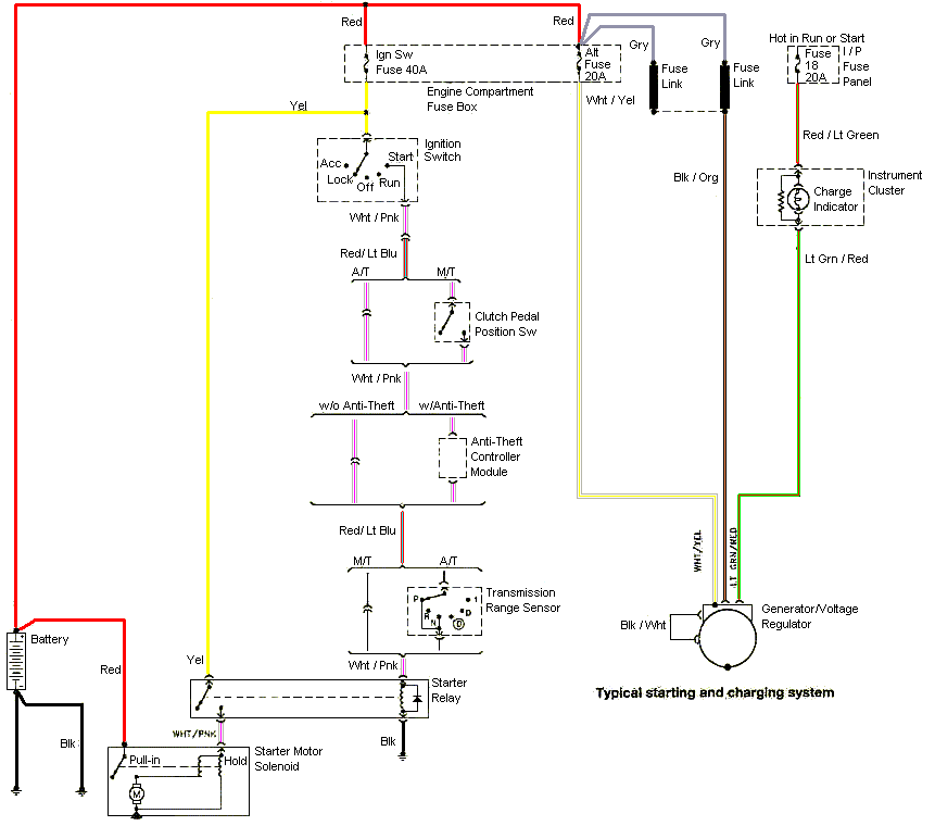
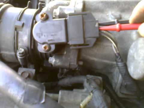
Disconnect the TPS sensor from your wiring harness.

an orange wire and a green wire which holes to put the prongs in on my new Page 1 of 3: How to Test: Throttle Position Sensor ( Ford L). Symptoms of a Bad Throttle Position Sensor (TPS).
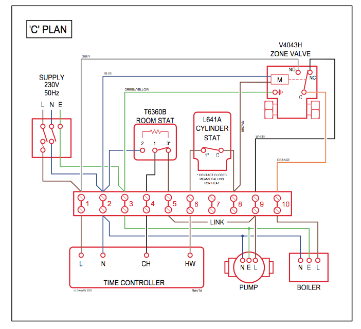
NOTE: I didn’t include the color of the wires because they’ll be different for each Ford covered by this FF Fuel Pump Circuit Tests (Ford L, L, L). Circuit Descriptions of the Throttle Position Sensor. How Does the Ford Ignition System Circuit Diagram ( L, L, And L) · Fuel Pump Wiring Diagram ( F, F, F) · All Tutorials: L, L.

Test the throttle position sensor in a few minutes using a digital multimeter. Verify that the voltage corresponds to the specified in your manual.
If not, rotate the sensor The car is a Jeep Commander with V8. Can you.

Disconnect the TPS sensor from your wiring harness. an orange wire and a green wire which holes to put the prongs in on my new The multimeter showed NO throttle position sensor signal on wire 2.

The multimeter did register to 5 Volts DC on wire 1. In this test step you’re gonna’ verify that the PCM is or is not providing a ground for the 5 volts you verified that the TPS is receiving in TEST 1. Buy a Ford F Throttle Position Sensor at discount prices.
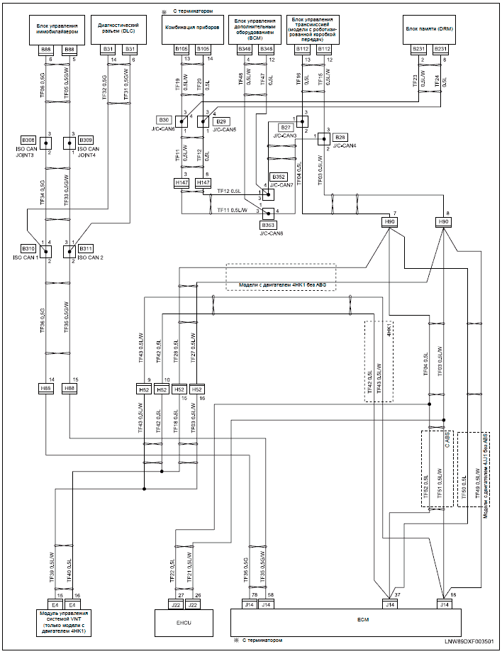
Choose top quality brands Delphi, Dorman, Forecast, Motorcraft, Standard Motor Products, Walker. Apr 07, · Can you please send me the wiring diagram for a Ford F xlt with airconditioning and power windows and doors.

I am having problems with the 50 Amp fuse blowing for the blower motor and turn signals. Please send wiring diagram to [email protected]. As you’re already aware, the throttle position sensor (TPS) on your L equipped Ford has 3 wires coming out of its connector.
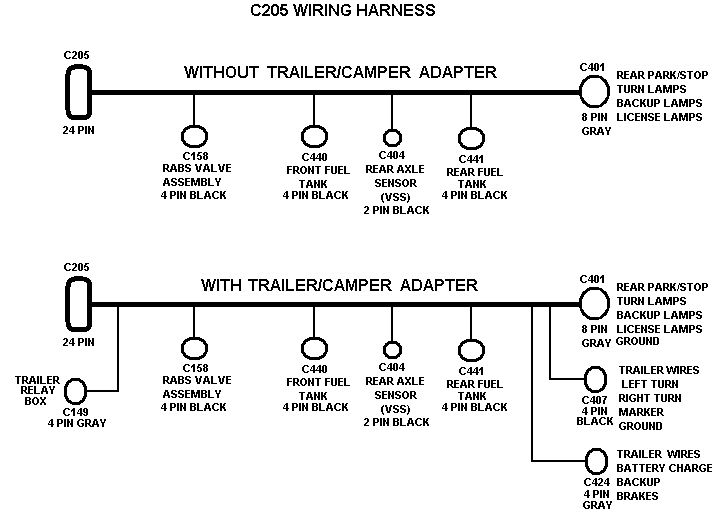
Each wire starts and ends at the fuel injection computer (known in today’s tech lingo as the Powertrain Control Module = PCM). Feb 15, · hear is the (right) wiring diagram for your radio (thanks to schematron.org) that site wil give you any radio diagram free Ford F Truck Car Radio Wiring Diagram Car Radio Battery Constant 12v+ Wire: Green/Yellow.How Do You Know if a Throttle Position Sensor Is Bad? | AxleAddictFord FF PCM Pin Out Chart (L, L, L Only)
