BL Touch is a popular auto bed leveling sensor used in 3D printers to ensure that the print bed is perfectly level before every print. It uses a probe to measure the distance between the nozzle and the bed at multiple points, and then adjusts the printing process accordingly to compensate for any variations in bed level.
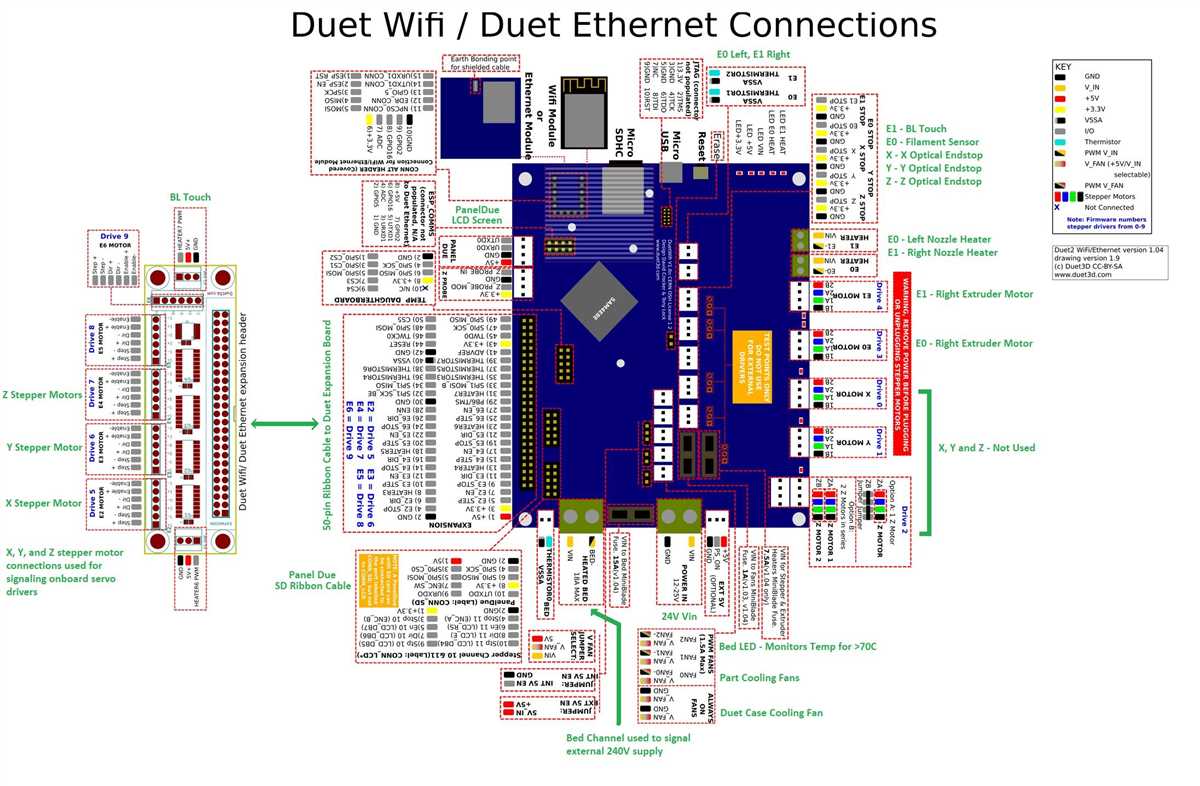
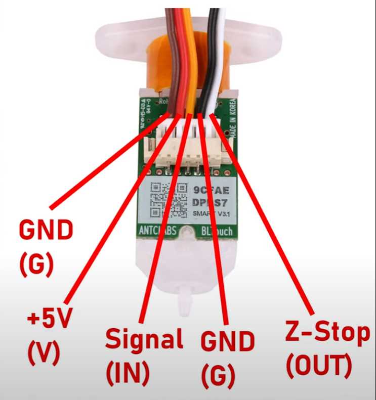
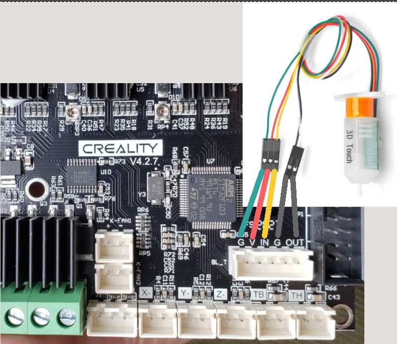
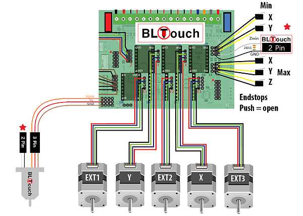
Wiring the BL Touch sensor in a 3D printer can be a bit confusing for beginners, but with the right diagram and instructions, it can be done easily. The BL Touch wiring diagram provides a visual representation of how the sensor should be connected to the printer’s control board and the power supply.
Before starting the wiring process, it is important to check the compatibility of the BL Touch sensor with your 3D printer model. Different printers have different wiring configurations, so it’s essential to find the correct wiring diagram for your specific printer model.
The BL Touch wiring diagram typically consists of labeled pins for the BL Touch sensor, the control board, and the power supply. The diagram also shows the connections for various components such as the z-stop switch, the extruder, and the heated bed. It is important to follow the diagram carefully and ensure that each wire is connected to the correct pin to avoid any potential damage to the sensor or other components.
Understanding BL Touch
BL Touch is an automatic bed leveling sensor for 3D printers that helps ensure proper and consistent bed leveling. It uses a probe to detect the distance between the nozzle and the bed, allowing the printer to make adjustments accordingly. This can greatly improve print quality and reduce the risk of failed prints.
The BL Touch sensor consists of a mechanical probe and a control board. The probe is attached to the print head and is deployed before each print to make contact with the bed. Once the probe touches the bed, it sends a signal to the control board, which then adjusts the Z-axis height based on the measured distance. This process is repeated several times to ensure an accurate leveling measurement.
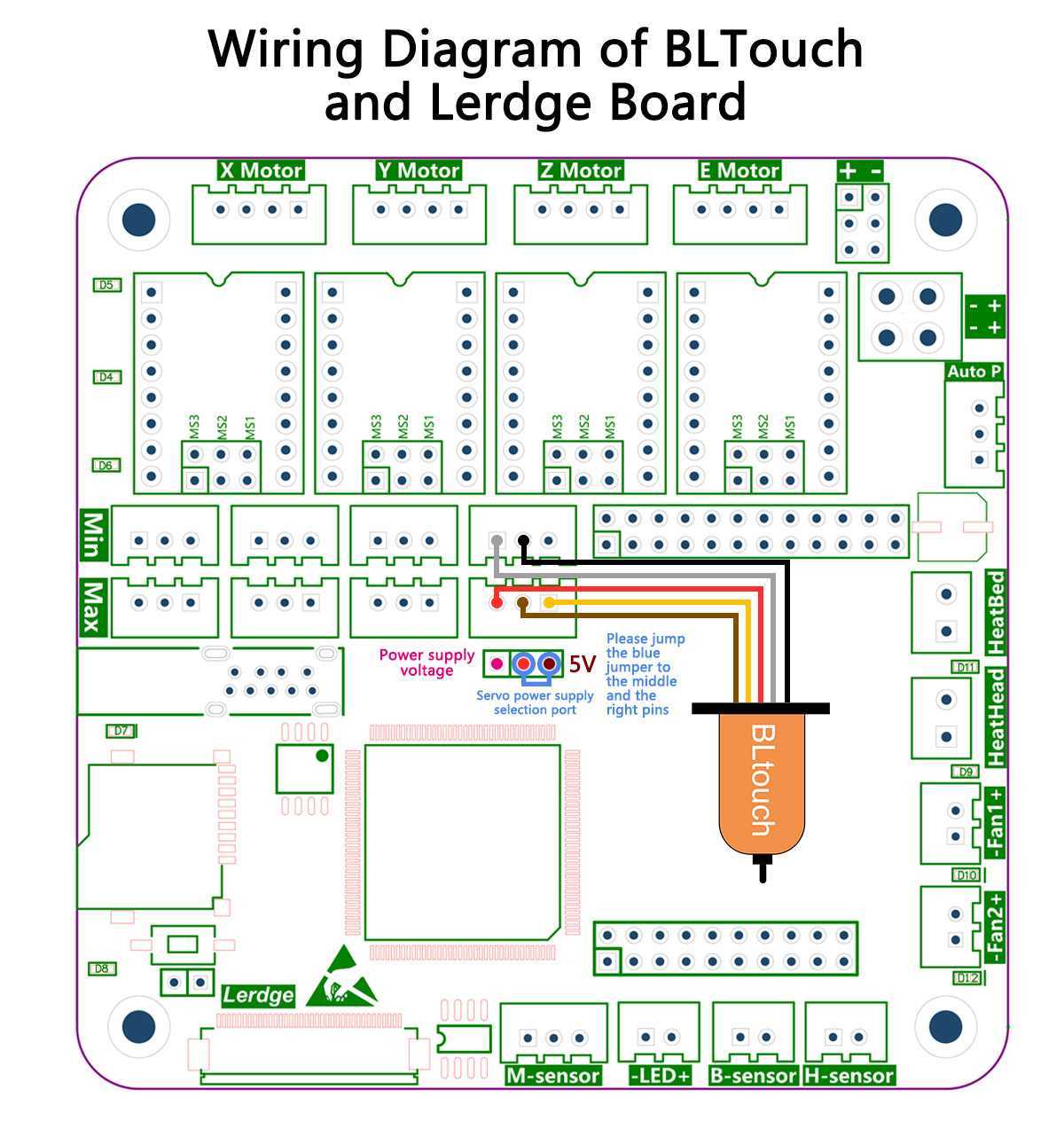
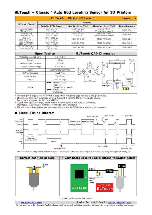
Understanding the wiring diagram of the BL Touch sensor is important for proper installation. The diagram typically shows the connection points between the sensor, control board, and other components of the 3D printer. It may include information on how to connect the signal, ground, and power wires, as well as any necessary modifications to the printer’s firmware.
When wiring the BL Touch sensor, it is crucial to follow the manufacturer’s instructions and to double-check the polarity of the wires. Incorrect wiring can result in malfunctioning or unreliable bed leveling. Additionally, it is recommended to secure and protect the wires to prevent any accidental damage during printing.
In summary, the BL Touch sensor is a valuable tool for achieving accurate bed leveling on 3D printers. Understanding its functionality and properly wiring it can lead to improved print quality and a smoother printing experience.
Wiring BL Touch to your Printer
When it comes to upgrading your 3D printer with a BL Touch sensor, it’s crucial to know how to correctly wire it to your printer’s electronics. The BL Touch is a popular auto-leveling sensor that helps ensure accurate printing by measuring the distance between the print bed and the nozzle. Here is a step-by-step guide on how to wire the BL Touch to your printer:
1. Identify the necessary wires:
Before starting the wiring process, make sure you have the required wires. The BL Touch typically comes with a set of three wires: red, black, and white. The red wire is for the 5-volt power supply, the black wire is for the ground connection, and the white wire is for the control signal.
2. Locate the appropriate pins on your printer’s mainboard:
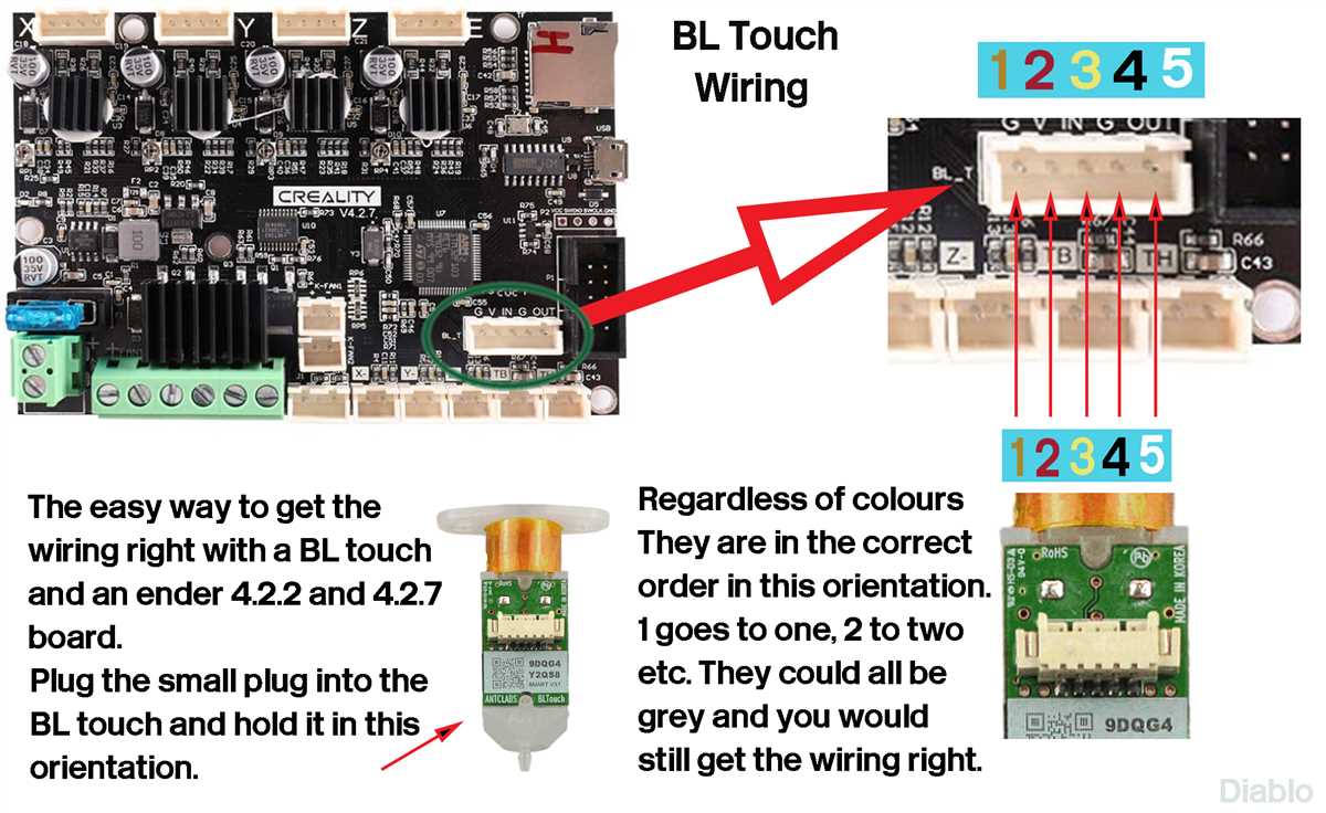
Find the appropriate pins on your printer’s mainboard for connecting the BL Touch. The exact location of these pins may vary depending on the printer model, so refer to your printer’s documentation or consult online resources for specific instructions.
3. Connect the wires:
Begin by connecting the red wire from the BL Touch to the 5-volt power supply pin on the mainboard. Next, connect the black wire to the ground pin. Finally, connect the white wire to the control signal pin.
4. Enable the BL Touch in your printer’s firmware:
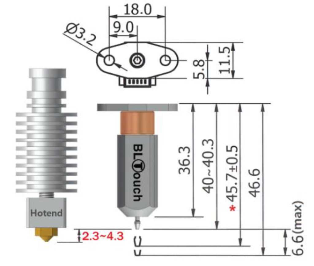
Once the wiring is complete, you need to enable the BL Touch functionality in your printer’s firmware. This typically involves modifying and uploading a new firmware version that supports BL Touch. Again, refer to your printer’s documentation or online resources for instructions specific to your printer model.
With the BL Touch properly wired and configured, you can enjoy the benefits of auto-leveling and improved print accuracy on your 3D printer. Remember to follow proper safety precautions and consult professional help if you are unsure about any step in the wiring process.
Connecting BL Touch to the Mainboard
Connecting the BL Touch sensor to the mainboard of your printer is a crucial step in enabling automatic bed leveling and improving print accuracy. The BL Touch is a popular choice for 3D printer enthusiasts as it can accurately measure the distance between the printer’s nozzle and the print bed, ensuring optimal print quality.
The wiring diagram for connecting the BL Touch to the mainboard may vary depending on the specific model of your printer and mainboard. However, the basic connections generally remain the same. You will need to connect the BL Touch sensor to the appropriate pins on the mainboard, usually labeled as Z-min, GND, and 5V.
Here’s a step-by-step guide on how to connect the BL Touch sensor to the mainboard:
- First, locate the Z-min, GND, and 5V pins on your mainboard. Consult the user manual or documentation of your printer if you are unsure about the pin locations.
- Next, connect the signal wire of the BL Touch to the Z-min pin on the mainboard. This wire is typically colored white or yellow and carries the data signal from the sensor to the mainboard.
- Connect the ground wire of the BL Touch to the GND pin on the mainboard. This wire is usually colored black or brown and provides the ground connection for the sensor.
- Finally, connect the power wire of the BL Touch to the 5V pin on the mainboard. This wire is typically colored red and supplies the sensor with the necessary power.
After completing the wiring connections, you may need to update the firmware of your printer to enable support for the BL Touch sensor. Consult the documentation or online resources for your specific printer model to learn how to update the firmware.
By correctly connecting the BL Touch sensor to the mainboard, you can take advantage of its automatic bed leveling capabilities and enjoy improved print quality and convenience during your 3D printing projects.
Configuring Firmware for BL Touch
When using the BL Touch for auto bed leveling on your 3D printer, it is important to properly configure the firmware to ensure accurate and reliable results. Here are the steps you need to follow to configure the firmware:
1. Connect BL Touch to the Control Board
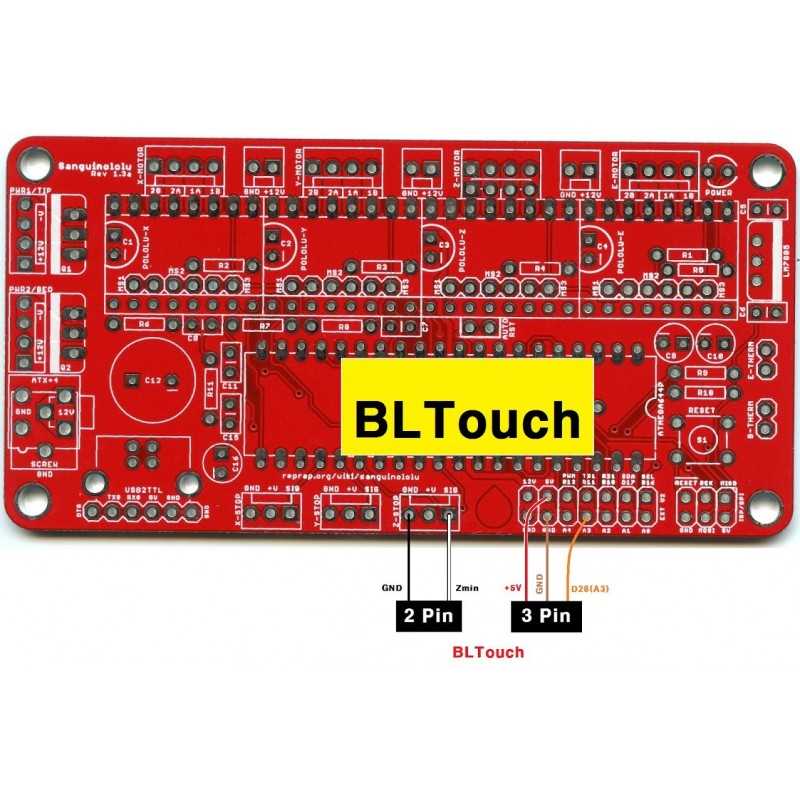
Start by connecting the BL Touch sensor to the control board of your 3D printer. Most control boards have designated pins for BL Touch, and you will need to connect the sensor to these pins using jumper wires. Consult the wiring diagram of your specific control board to determine the correct pins.
2. Modify Configuration.h
Next, you will need to modify the configuration.h file in your printer’s firmware to enable BL Touch support. Open the configuration.h file using a text editor and search for the line that says “#define AUTO_BED_LEVELING_FEATURE.” Uncomment this line by removing the “//” at the beginning.
Further down in the configuration.h file, find the section that says “BED_LEVELING_METHOD” and set it to “3” for BL Touch. This tells the firmware to use the BL Touch sensor for bed leveling.
3. Configure Probe Offset
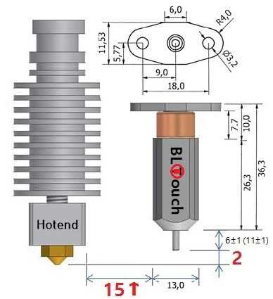
In the configuration.h file, locate the section that says “Probe offset from the nozzle” and enter the values for X, Y, and Z coordinates. These values specify the offset between the BL Touch sensor and the printer’s nozzle. Measure the actual distance and adjust the values accordingly.
4. Calibrate and Test
After configuring the firmware, upload it to your 3D printer and power it on. Perform a calibration and test your BL Touch sensor to ensure it is functioning correctly. Follow the manufacturer’s instructions for calibrating the BL Touch and adjust the sensor’s settings if necessary.
Once the calibration is complete, you can start using the BL Touch for automatic bed leveling before each print, ensuring optimal first layers and improved print quality.
Troubleshooting BL Touch Wiring
The BL Touch is a popular automatic bed leveling sensor used in 3D printers. Proper wiring is crucial for the BL Touch to function correctly. However, sometimes there can be issues with the wiring connections, resulting in the sensor not working properly. In this troubleshooting guide, we will discuss common problems and their possible solutions.
1. Loose or Incorrect Wiring Connections
A common issue with the BL Touch wiring is loose or incorrect connections. Make sure that all the wires are properly connected to the correct pins on the printer’s control board. Check the wiring diagram provided by the manufacturer to ensure correct connections. If the connections are loose, reseat them properly. If the connections are incorrect, refer to the wiring diagram to correct them.
2. Damaged or Broken Wires
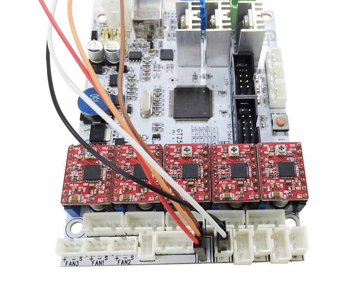
Another possible issue is damaged or broken wires. Inspect the wires connected to the BL Touch for any signs of damage or breakage. If any wires are damaged, replace them with new ones. Ensure that the replacement wires are of the correct gauge and properly insulated.
3. Insufficient Power Supply
In some cases, the BL Touch may not work properly if the printer’s power supply is insufficient. Check if the power supply is providing enough voltage and current to properly operate the BL Touch. If the power supply is not adequate, consider upgrading to a higher-capacity power supply.
4. Firmware Configuration
Incorrect firmware configuration can also cause issues with the BL Touch. Ensure that the firmware is configured correctly to support the BL Touch sensor. Refer to the printer’s manual or the manufacturer’s website for the correct firmware settings. If necessary, update the firmware to the latest version that supports the BL Touch.
5. Faulty BL Touch Sensor
If all the wiring connections are correct and the firmware is properly configured, but the BL Touch still does not work, it is possible that the sensor itself is faulty. Contact the manufacturer or the vendor from whom you purchased the BL Touch for further assistance. They may provide troubleshooting steps or offer a replacement if the sensor is indeed faulty.
In conclusion, troubleshooting BL Touch wiring requires checking for loose or incorrect wiring connections, inspecting for damaged or broken wires, ensuring sufficient power supply, verifying firmware configuration, and considering a faulty sensor as the last possibility. By following these troubleshooting steps, you can identify and resolve issues with the BL Touch sensor’s wiring and get your 3D printer back to proper functioning.