
Understanding the wiring diagram of an electric motor is essential for anyone new to the world of electrical engineering or DIY projects. Whether you are planning to install a new motor or troubleshoot an existing one, having a clear understanding of how the wiring is laid out can save you time, effort, and avoid potential hazards. In this article, we will break down the components and symbols found in a typical electric motor wiring diagram, and explain how they are connected.
Firstly, it is important to understand that an electric motor may have various types of wiring diagrams depending on its purpose and design. However, there are some common elements that you will find in most diagrams. These include power supply connections, control circuit connections, protection devices, and motor connections.
The power supply connections are responsible for delivering electrical energy to the motor. This may involve connecting the motor to a single-phase or three-phase power source, depending on the motor’s requirements. The control circuit connections allow for the control and regulation of the motor’s speed, direction, or other parameters. Protection devices, such as fuses or circuit breakers, are included to prevent damage to the motor or surrounding equipment in case of electrical faults. The motor connections refer to the terminals that connect the motor to its power supply and control circuitry.
In a wiring diagram, these components are represented by various symbols and labels. For example, power supply connections are usually denoted by an upward arrow labeled with the appropriate voltage and phase. Control circuit connections may be represented by switches, relays, or other components, depending on the complexity of the motor’s control system. Protection devices are often depicted by symbols such as fuse or circuit breaker icons. Motor connections are typically shown as numbered terminals or wires labeled with their respective phase or function.
By understanding the various components and symbols found in a wiring diagram, you can decipher how an electric motor is wired and troubleshoot any issues that may arise. It is important to note that wiring diagrams can vary depending on the manufacturer or specific motor model, so always refer to the provided documentation for accurate information. However, with a basic understanding of the principles and symbols involved, even beginners can navigate and comprehend a typical electric motor wiring diagram.
What is a Wiring Diagram Electric Motor?
An electric motor is a device that converts electrical energy into mechanical energy. It is used in various applications, such as industrial machinery, household appliances, and automotive systems. To properly install and connect an electric motor, a wiring diagram is essential. A wiring diagram electric motor is a visual representation of the electrical connections and components associated with a motor.
A wiring diagram electric motor typically includes information such as the power supply, motor terminals, control circuit, and other relevant components. It shows the interconnections between these components, allowing technicians and electricians to understand how the motor should be wired and connected. This diagram plays a crucial role in ensuring the motor operates efficiently and safely.
The wiring diagram electric motor may also include additional details, such as the motor’s rated voltage, current, and power, as well as any specific instructions for wiring and troubleshooting. It is important to follow the wiring diagram provided by the manufacturer or follow industry standards to prevent any electrical hazards or damage to the motor.
Key components of a wiring diagram electric motor:
- Power supply: Indicates the source of electrical energy that powers the motor.
- Motor terminals: Shows the terminals where the electrical connections are made.
- Control circuit: Illustrates the components and wiring for controlling the motor’s operation, such as switches, relays, and control panels.
- Protection devices: Includes components like fuses, circuit breakers, and overload relays to protect the motor from excessive current or electrical faults.
- Grounding: Depicts the grounding connections necessary for safety and proper operation of the motor.
In summary, a wiring diagram electric motor is a visual representation that guides the installation and connection of an electric motor. It allows technicians and electricians to understand the electrical connections and components associated with the motor, ensuring safe and efficient operation.
Learn the Basics of Wiring Diagram Electric Motor
When working with electric motors, it is important to understand the wiring diagram in order to properly install and troubleshoot the motor. The wiring diagram is a visual representation of the electrical connections and functions of the motor, and it provides crucial information for electricians and technicians.
A wiring diagram electric motor typically includes various components such as power supply, motor, starter, and control circuitry. It shows the path of electrical currents and helps identify the different wires and their functions. The diagram may also include symbols and labels to indicate the type of wire or connection, as well as any additional devices or components.
Understanding the wiring diagram:
- Power supply: The wiring diagram will show the source of power for the motor, whether it is AC or DC voltage.
- Motor: The diagram will indicate the different terminals and connections of the motor, such as the main winding, auxiliary winding, and any capacitors or switches.
- Starter: If the motor requires a starter, the wiring diagram will show the connections for the starter, including any overload relays or contactors.
- Control circuitry: The diagram may include the control circuitry for the motor, such as push buttons, switches, and relays.
Using the wiring diagram:
By studying the wiring diagram, technicians can understand how the motor is wired and troubleshoot any issues that may arise. They can identify which wires carry power, which ones are for control circuits, and ensure that all connections are correct.
When installing a motor, electricians can refer to the wiring diagram to make sure they are connecting the wires properly and following the manufacturer’s instructions. They can also use the diagram to check for any potential issues, such as short circuits or incorrect connections.
In conclusion, understanding the basics of the wiring diagram for an electric motor is essential for proper installation and troubleshooting. It provides valuable information about the electrical connections and functions of the motor, enabling electricians and technicians to work safely and efficiently.
Why is a Wiring Diagram Electric Motor Important?
An electric motor is a complex piece of machinery that requires precise wiring for proper functioning. A wiring diagram for an electric motor is an essential tool that outlines the connections and electrical components involved in the motor’s operation. It provides a visual representation of the motor’s circuitry, allowing technicians to troubleshoot, repair, and maintain the motor effectively.
Identification and organization of components: A wiring diagram electric motor helps in identifying and organizing the various components of the motor’s electrical system. It shows the layout of the motor’s terminals, wires, switches, relays, and other electrical components, making it easier to understand the motor’s configuration. This information is vital for technicians to diagnose and resolve any issues that may arise during operation.
Troubleshooting electrical problems: Electrical problems can occur in electric motors due to various reasons, such as faulty connections, damaged wires, or malfunctioning components. A wiring diagram helps technicians quickly locate and isolate the problem areas by providing a clear overview of the motor’s wiring and connections. With this information, they can test specific components, check for continuity, and determine the root cause of the issue.
Ensuring safe operation: Proper wiring is crucial for the safe operation of an electric motor. A wiring diagram helps technicians follow the correct wiring procedures, ensuring that the motor is correctly grounded, all connections are secure, and electrical hazards are minimized. Following the wiring diagram helps prevent accidents, such as electrical shocks or fires, and ensures that the motor operates reliably and efficiently.
Understanding motor functionality: A wiring diagram electric motor provides insight into the functionality of the motor and how it interacts with other electrical devices or systems. By understanding the circuitry and connections, technicians can make informed decisions about motor control, speed regulation, and electrical integration. This knowledge not only enhances troubleshooting abilities but also allows for customization and optimization of the motor’s performance.
Overall, a wiring diagram electric motor plays a vital role in the proper functioning, maintenance, and safety of an electric motor. It serves as a roadmap, guiding technicians through the motor’s electrical system and enabling them to diagnose and resolve any issues efficiently. Investing time in understanding and using wiring diagrams can save time, prevent accidents, and prolong the lifespan of electric motors.
Understanding Different Types of Wiring Diagrams for Electric Motors
Electric motors are vital components in various industries and applications, and understanding their wiring diagrams is crucial for proper installation, maintenance, and troubleshooting. There are different types of wiring diagrams available for electric motors, each serving a specific purpose. Let’s explore some of these wiring diagrams to gain a better understanding:
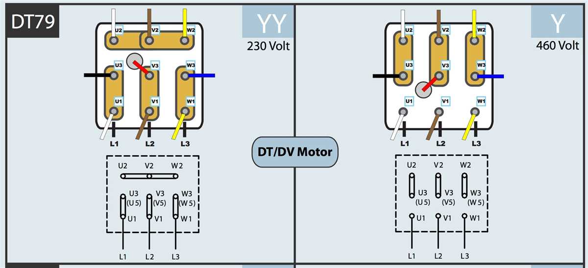
1. Connection Diagrams
The connection diagram, also known as the terminal diagram or schematic diagram, provides a visual representation of the electrical connections between the motor and its power supply. It shows the arrangement of the motor’s internal components, such as windings and terminals, and how they are connected to external devices, such as switches and control panels. Connection diagrams are essential for understanding the correct wiring configuration of an electric motor.
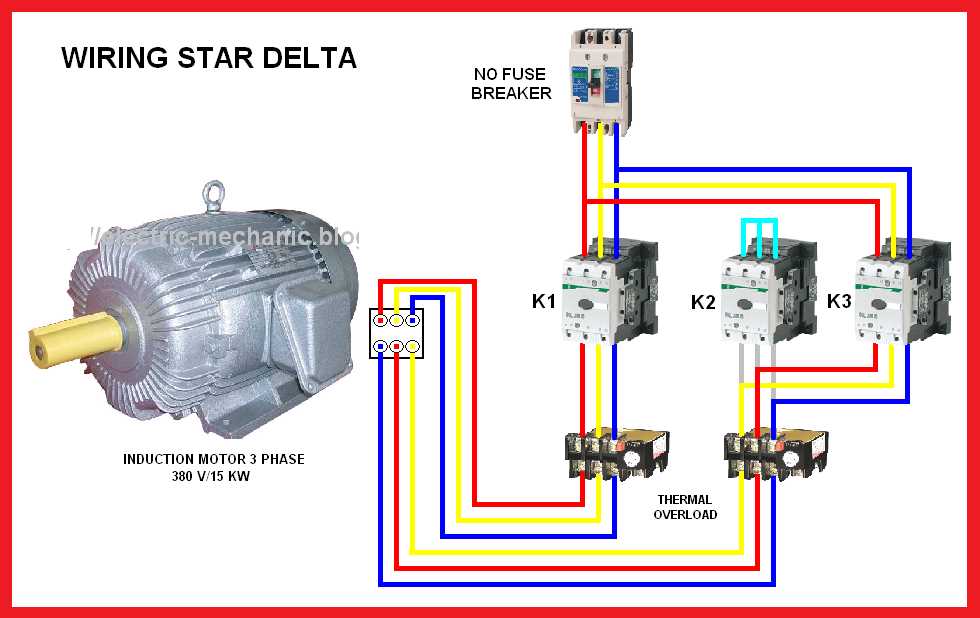
2. Control Circuit Wiring Diagrams
Control circuit wiring diagrams focus on the wiring connections between the motor and the control panel or PLC (Programmable Logic Controller). These diagrams provide a detailed view of the electrical circuits and devices involved in controlling the motor’s operation, such as relays, contactors, and push buttons. Control circuit wiring diagrams help technicians troubleshoot and repair control system issues and ensure proper functionality.
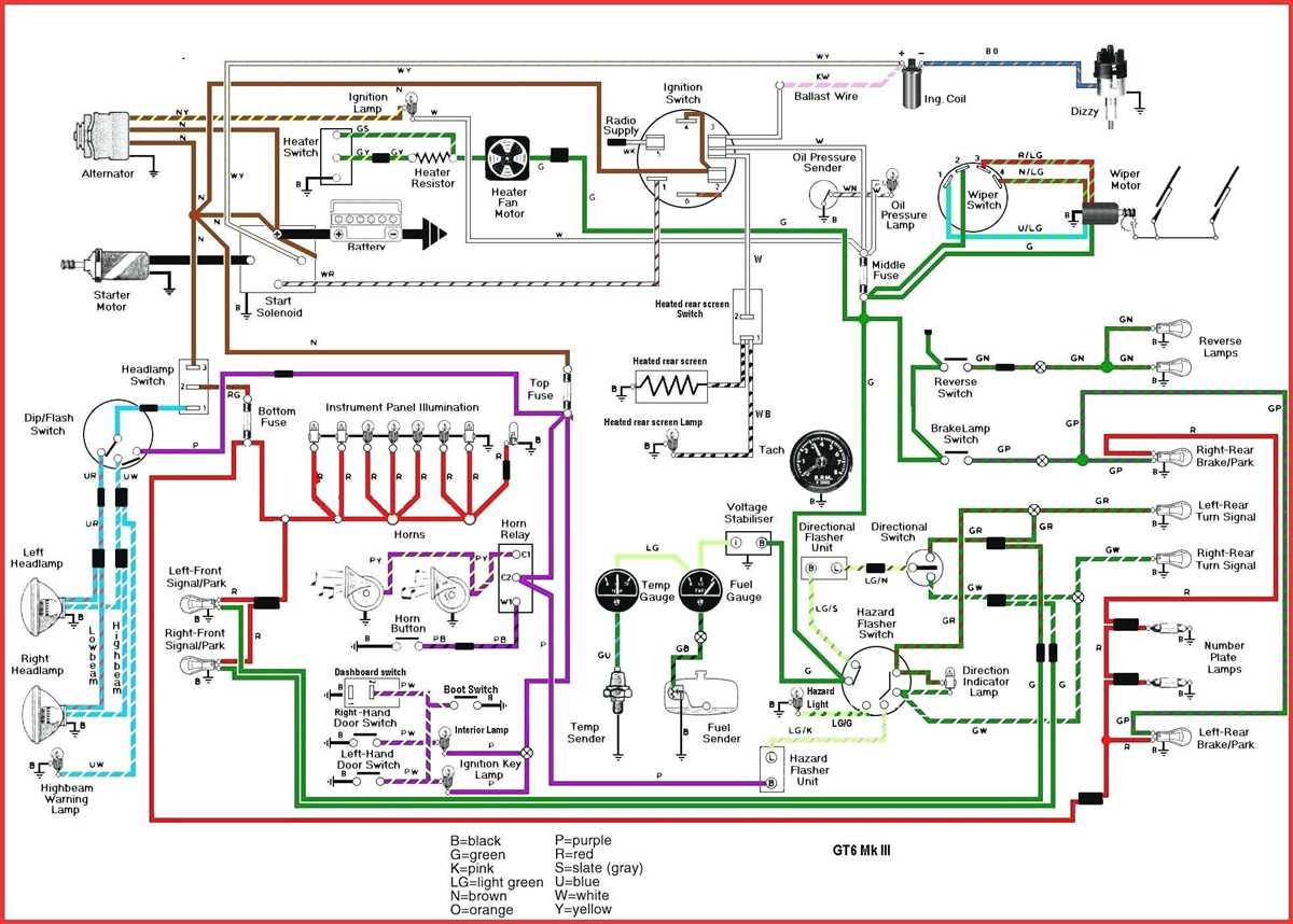
3. Line Diagrams
Line diagrams, also referred to as ladder diagrams or schematic diagrams, illustrate the electrical connections and logical sequence of operation within the motor control circuit. They use symbols and lines to represent various devices and their interconnections, making it easier to understand the overall circuit layout. Line diagrams are commonly used in industrial settings and are essential for designing, installing, and maintaining motor control systems.
4. Connection Diagrams for Specific Applications
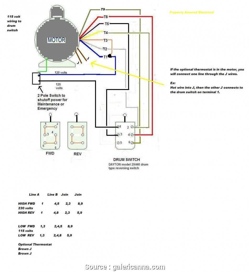
In certain applications, electric motors require specific wiring configurations to meet specific requirements. These specialized connection diagrams provide instructions on how to wire the motor for specific functions, such as reversing the direction of rotation or connecting it to variable speed drives. These diagrams are tailored to the unique needs of the application and are crucial for ensuring optimal motor performance.
5. Manufacturer’s Diagrams
Lastly, it’s essential to consult the manufacturer’s wiring diagrams specific to the motor being used. These diagrams are designed by the motor manufacturer and provide accurate and detailed information on the motor’s wiring connections, including any specific requirements or recommendations. Manufacturer’s diagrams are the most reliable source of information when working with electric motors.
In conclusion, understanding the different types of wiring diagrams for electric motors is essential for safe and efficient motor installation, maintenance, and troubleshooting. Whether it’s connection diagrams, control circuit wiring diagrams, line diagrams, specialized application diagrams, or manufacturer’s diagrams, these resources provide valuable information for working with electric motors.
Tips and Tricks for Reading and Interpreting Wiring Diagram Electric Motor
When it comes to working with electric motors, understanding wiring diagrams is essential. Wiring diagrams provide a visual representation of the electrical connections and components in the motor. Here are some tips and tricks to help you read and interpret wiring diagrams for electric motors.
Familiarize yourself with the symbols: Wiring diagrams use symbols to represent various components and connections. Before diving into a wiring diagram, make sure you are familiar with the symbols used in the diagram. This will help you understand the different elements and connections in the motor.
Follow the flow of the diagram: Wiring diagrams typically have a flow from left to right, showing the progression of electrical connections. Start at the left side of the diagram and follow the lines and symbols to see how the components are connected.
Pay attention to the color codes: Colors are often used in wiring diagrams to represent different electrical connections. Understanding the color codes can help you identify the correct wires and connections in the motor. Refer to the legend or key provided in the diagram to decode the colors.
Identify the main components: Look for the main components in the wiring diagram, such as the motor itself, power supply, switches, and relays. Understanding how these components are connected is crucial for troubleshooting and repairing the motor.
Take note of the connections: Wiring diagrams usually show the specific connections between components, such as the motor’s terminals and the power supply. Pay close attention to these connections and ensure they match the wiring in the actual motor.
Use a magnifying glass if needed: Some wiring diagrams may have small symbols or labels that are hard to read. If you are having trouble deciphering the details, use a magnifying glass to enlarge the diagram and make it easier to read.
Refer to the manufacturer’s documentation: If you are unsure about any aspect of the wiring diagram, consult the manufacturer’s documentation for the specific motor model. The documentation often provides additional information and explanations that can help you understand the wiring diagram better.
By following these tips and tricks, you will be able to read and interpret wiring diagrams for electric motors with greater ease and accuracy. This knowledge will empower you to troubleshoot and repair motors more effectively, saving time and money in the process.
Common Wiring Mistakes to Avoid When Working with Electric Motors
When working with electric motors, it is important to be aware of and avoid common wiring mistakes. These mistakes can lead to equipment failure, electrical hazards, and even fires. To ensure the safety and functionality of your electric motor, here are some common wiring mistakes you should avoid:
1. Incorrect Wiring Connections
One of the most common mistakes is making incorrect wiring connections. This can include reversing the polarity, connecting wires to the wrong terminals, or not following the proper wiring diagram. Incorrect wiring connections can cause the motor to operate in the wrong direction, overheat, or not work at all.
2. Inadequate Wire Sizing
Another common mistake is using wires that are too small for the electrical load. Inadequate wire sizing can lead to overheating, voltage drop, and equipment damage. It is important to consult the motor’s documentation or an electrician to determine the appropriate wire size for your specific application.
3. Neglecting Grounding and Bonding
Proper grounding and bonding are essential for safety and protection against electrical shock. Neglecting to properly ground and bond the motor can lead to electrical malfunctions and increased risk of electric shock. Always follow the manufacturer’s instructions and local electrical codes when it comes to grounding and bonding.
4. Overlooking Insulation Integrity
Insulation integrity is crucial for preventing short circuits and electrical failures. Overlooking insulation integrity can result in wires coming into contact with each other or with the motor’s housing, leading to electrical faults and potential hazards. Regularly inspect the insulation on your motor’s wiring to ensure it is in good condition and make any necessary repairs or replacements.
5. Lack of Proper Wire Protection
Failure to provide proper wire protection can expose the wires to damage and increase the risk of electrical accidents. Make sure to use appropriate conduit, loom, or other protective measures to shield the motor’s wiring from physical harm, such as abrasion, moisture, or excessive heat.
Avoiding these common wiring mistakes is crucial for the safe and efficient operation of electric motors. Always follow the manufacturer’s instructions, consult professionals when needed, and prioritize safety when working with electrical systems.