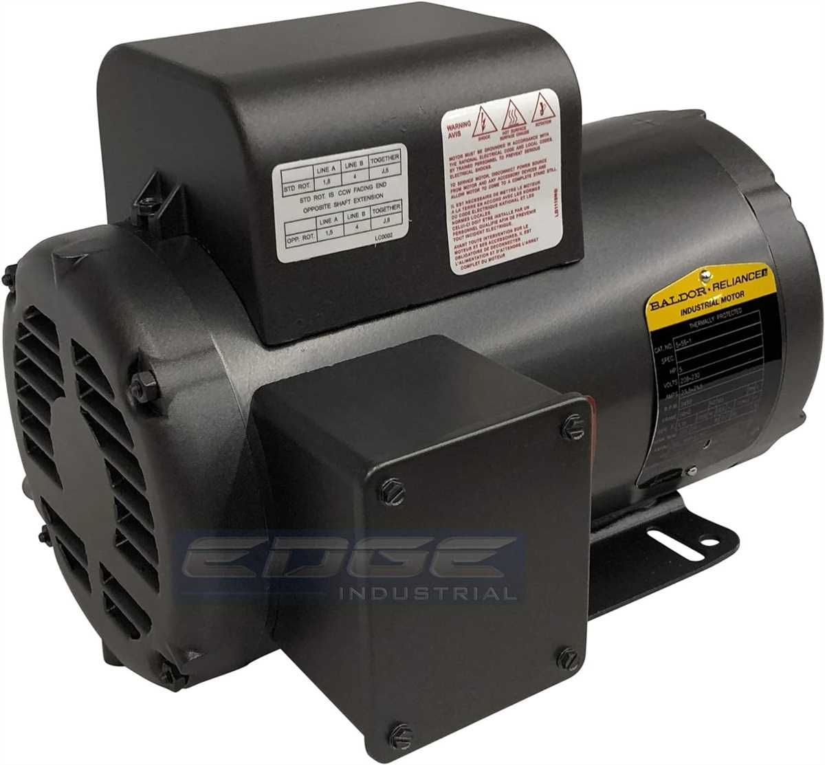
If you’re looking to wire a Baldor 3 hp motor, you’ve come to the right place. In this article, we’ll provide you with a comprehensive wiring diagram to help you navigate through the process. Whether you’re an experienced electrician or just starting out, understanding the proper wiring for your motor is essential for its proper functioning.
Baldor is a trusted brand when it comes to motors, and their 3 hp motor is no exception. It is commonly used in various applications, such as in industrial machinery, compressors, and pumps. Properly wiring the motor ensures that it receives the correct voltage and current, allowing it to run efficiently and safely.
The wiring diagram for a Baldor 3 hp motor typically includes information on how to connect the motor’s power leads, control leads, and grounding connections. It is important to carefully follow the diagram’s instructions and adhere to the local electrical code regulations. Failure to do so can result in damage to the motor or even pose a safety risk.
By understanding and correctly wiring your Baldor 3 hp motor, you can ensure its longevity and optimal performance. So, let’s dive into the wiring diagram and get your motor up and running smoothly!
Understanding the basics of a Baldor 3 hp motor
A Baldor 3 hp motor is a powerful motor used in various industrial applications. It is known for its durability and reliability, making it a popular choice for many businesses. To properly understand how this motor works, it is important to familiarize yourself with its basic components and wiring diagram.
The Baldor 3 hp motor consists of several key components, including the stator, rotor, and bearings. The stator is the stationary part of the motor that contains the windings. These windings are made up of insulated copper wires and are responsible for creating a magnetic field when an electrical current is passed through them. The rotor, on the other hand, is the rotating part of the motor that is connected to the load. It is typically made of laminated iron cores and copper bars, which help conduct the electrical energy.
The wiring diagram of a Baldor 3 hp motor provides a visual representation of how the various components are connected. It typically includes information on the motor’s voltage, amperage, and speed ratings, as well as the proper wiring connections for the power supply. This diagram is crucial for ensuring the motor is wired correctly and functions efficiently.
Key components and wiring connections:
- Power supply: The motor is typically powered by an electrical power supply, such as a three-phase AC source. The voltage and frequency of the power supply must match the motor’s rating for proper operation.
- Motor terminals: The motor terminals are where the power supply wires are connected. These terminals are typically labeled with letters or numbers for easy identification.
- Contactor or starter: A contactor or starter is used to control and protect the motor. It is responsible for connecting and disconnecting the power supply to the motor.
- Thermal overload relay: The thermal overload relay is a protective device that monitors the motor’s temperature. It protects the motor from overheating by cutting off the power supply if the temperature exceeds a certain limit.
- Grounding: Proper grounding is essential for electrical safety. The motor should be grounded to prevent electric shock and protect the motor from electrical faults.
Understanding the basics of a Baldor 3 hp motor, including its components and wiring diagram, is crucial for proper installation and operation. It is important to follow the manufacturer’s guidelines and consult the wiring diagram to ensure the motor is wired correctly and functions safely and efficiently. Regular maintenance and inspections are also recommended to prolong the motor’s lifespan and prevent any potential issues.
Identifying the different parts of the motor
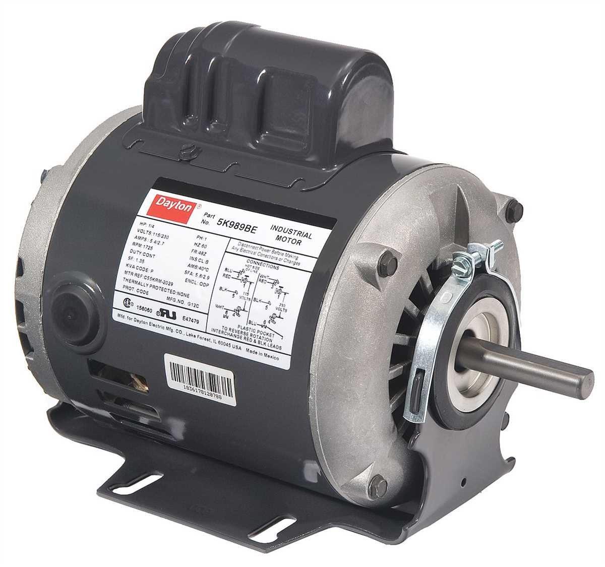
The Baldor 3 hp motor consists of several important parts that work together to provide power and drive machinery. Understanding these parts is essential for proper installation, troubleshooting, and maintenance.
1. Motor Frame: The motor frame serves as the main structural component of the motor, providing support and protection to the internal parts. It is typically made of durable materials like cast iron or aluminum.
2. Stator: The stator is the stationary part of the motor that contains the winding in which electrical current flows. It is usually made up of laminated steel sheets to minimize energy losses due to eddy currents.
3. Rotor: The rotor is the rotating part of the motor that interacts with the stator’s magnetic field to produce mechanical power. It is typically composed of a laminated core and conductive bars or coils.
4. Bearings: Bearings are used to support and facilitate the rotation of the motor shaft. They are typically located at both ends of the motor and can be either ball bearings or sleeve bearings.
5. Shaft: The shaft is the rotating rod that connects the rotor to the driven load. It transmits the mechanical power generated by the motor to the external equipment.
6. Capacitor: Some motors, including certain Baldor models, may incorporate capacitors to improve their starting torque and efficiency. These capacitors are connected in series or parallel with the windings.
7. Terminal Box: The terminal box is where the motor’s electrical connections are made. It provides a convenient location for wiring the motor to the power supply and includes terminals for connection to the main power lines.
By familiarizing yourself with these different parts of the Baldor 3 hp motor, you can better understand how the motor functions and diagnose any potential issues that may arise.
Wiring diagram for a Baldor 3 hp motor
When it comes to wiring a Baldor 3 hp motor, it is important to follow the correct diagram to ensure proper installation and functionality. The wiring diagram provides a visual representation of the electrical connections required for the motor to operate.
Below is a generalized explanation of the wiring diagram for a 3 hp Baldor motor:
- L1 and L2: These are the line voltage connections. They usually connect to the main power supply.
- T1 and T2: These are the motor terminals. They connect to the motor windings.
- T3 and T4: These are typically used for capacitor motors. They connect to the start winding and run winding of the motor.
- T5 and T8: These connections are often used in dual-voltage motors. They allow for different voltage options, depending on the wiring configuration.
- T9 and T10: These connections are used for reversing the motor direction. They are connected to the start winding and run winding in the opposite order to reverse the rotation.
- T11 and T12: Like T5 and T8, these connections are also used for dual-voltage motors. They provide additional voltage options, depending on the wiring configuration.
It is important to consult the specific wiring diagram provided by Baldor for your motor model. This diagram will provide detailed instructions on the correct connection points and configurations for your specific motor.
When wiring a Baldor 3 hp motor, it is recommended to consult a professional electrician or follow the guidelines provided in the motor’s user manual to ensure safe and correct installation.
Step-by-step instructions for wiring the motor
Wiring a Baldor 3 hp motor can be done by following a few simple steps. Here is a step-by-step guide on how to wire the motor:
1. Check the motor’s wiring diagram
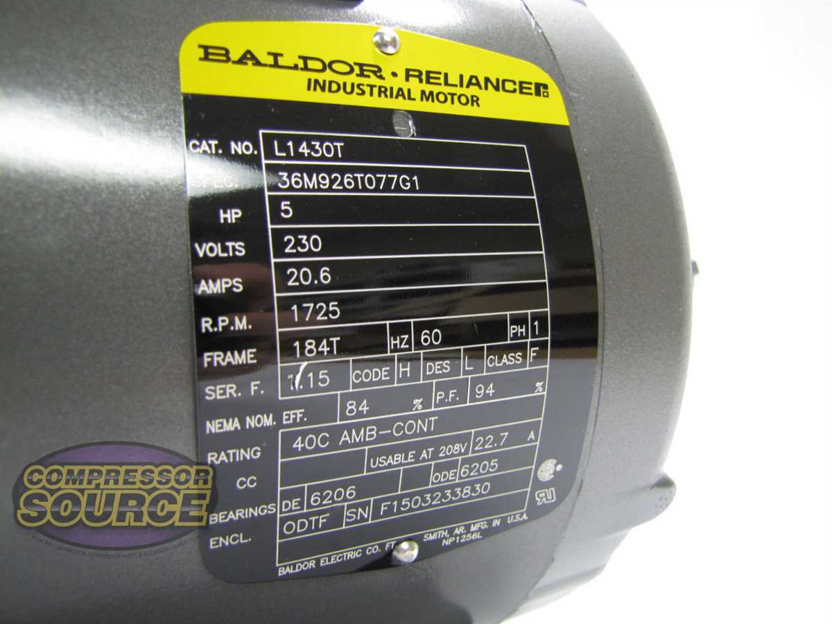
The first step in wiring a Baldor 3 hp motor is to check its wiring diagram. The wiring diagram is usually located on the motor’s nameplate or included in the motor’s documentation. The diagram will provide detailed instructions on how to connect the motor’s various wires.
2. Gather the necessary tools and materials
Before starting the wiring process, gather all the necessary tools and materials. This may include wire strippers, wire connectors, electrical tape, and a screwdriver. Make sure you have everything you need before proceeding.
3. Connect the power supply
The next step is to connect the power supply to the motor. This involves connecting the hot wire (typically black) to one of the motor’s terminal screws and the neutral wire (typically white) to the other terminal screw. If the motor requires a ground wire, connect it to the designated ground terminal.
4. Connect the motor’s leads
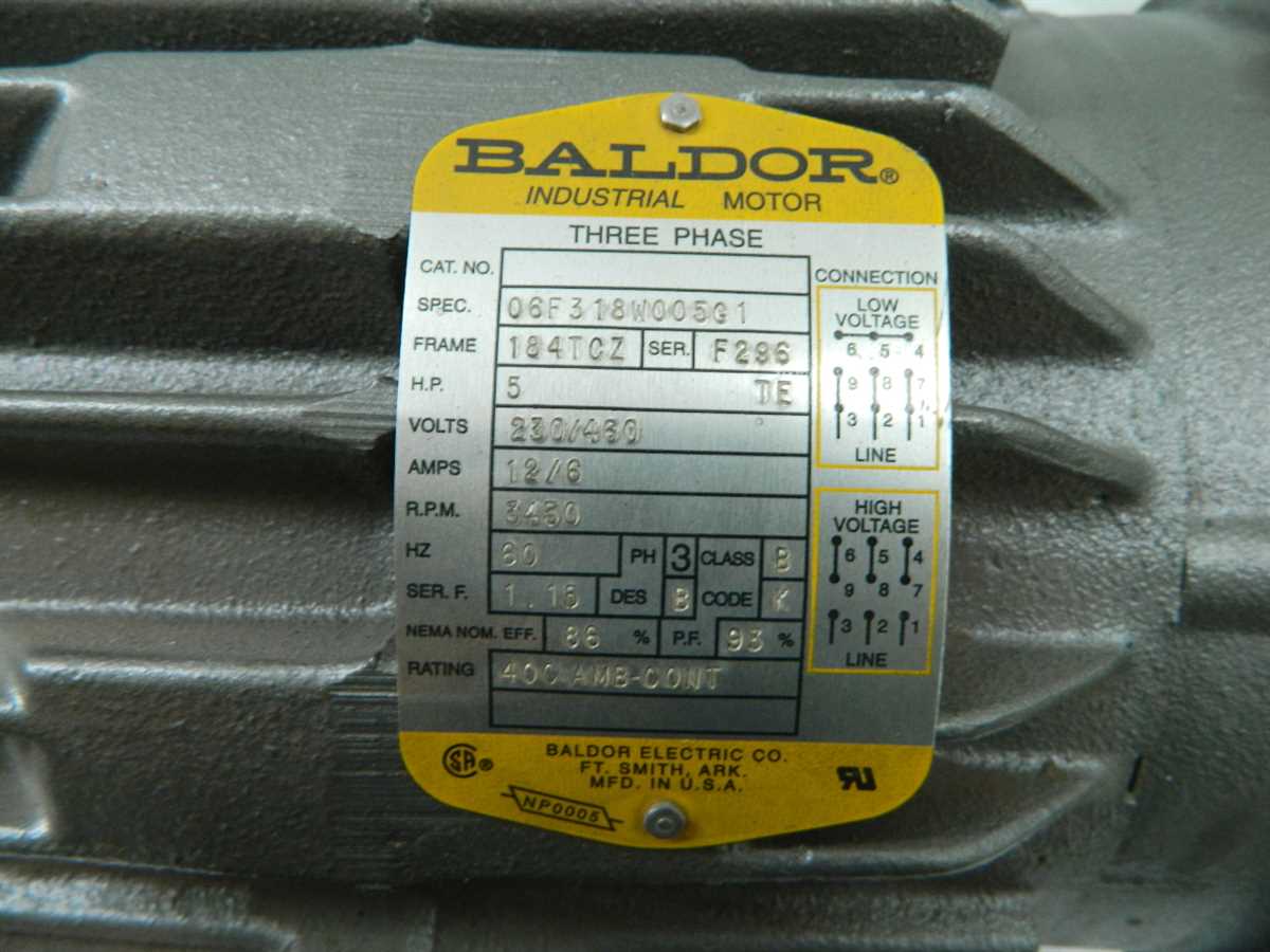
After connecting the power supply, proceed to connect the motor’s leads. The wiring diagram will indicate which leads should be connected to each other. Use wire connectors to make secure connections between the motor’s leads. Make sure to follow the wiring diagram carefully to ensure proper connections.
5. Insulate the connections
Once all the connections have been made, it is important to insulate them properly. Use electrical tape to cover any exposed wiring and prevent any accidental contact. This will help ensure safety and prevent any electrical hazards.
6. Test the motor
After completing the wiring process, it is important to test the motor to ensure it is functioning correctly. Connect the motor to a power source and observe its operation. If everything is working properly, the motor should run smoothly without any issues.
Following these step-by-step instructions will help you successfully wire a Baldor 3 hp motor. Remember to always refer to the motor’s wiring diagram and follow all safety precautions when working with electrical equipment.
Troubleshooting common issues with Baldor 3 hp motor wiring
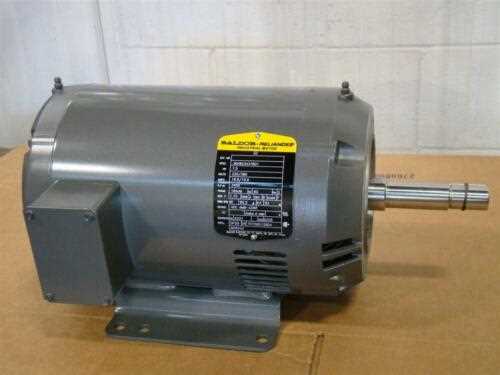
When it comes to troubleshooting issues with a Baldor 3 hp motor wiring, it is important to identify and address common problems that may arise. Understanding the wiring diagram and connections can help in troubleshooting the issues and finding a solution. Here are some common issues and tips for troubleshooting:
- No power: If the motor is not receiving any power, check the power supply and ensure it is properly connected and functioning. Also, make sure that the motor’s power switch is turned on.
- Tripped circuit breaker: In case the motor trips the circuit breaker, it could be due to an overload or a short circuit. Check if the motor is overloaded or if any wires are touching each other or the motor frame. If necessary, reduce the load on the motor or replace the faulty wires.
- Inconsistent speed: If the motor operates at inconsistent speeds, it could be a sign of wiring issues. Inspect the wiring connections, including the main power supply and terminal connections, and make sure they are secure and properly tightened. Loose connections can cause fluctuating speeds.
- Burnt smell or smoke: If there is a burnt smell or smoke coming from the motor, it may indicate a short circuit or overheating. Turn off the power supply immediately and inspect the wiring for any damaged or frayed wires. Replace any damaged wires or components before restarting the motor.
- Motor not starting: If the motor fails to start, it could be due to a faulty capacitor or a problem with the start winding. Check the motor’s wiring diagram and verify the connections. If necessary, test the capacitor or replace it, and inspect the start winding for any damage.
- Improper rotation: If the motor rotates in the wrong direction, it may be caused by incorrect wiring connections. Refer to the wiring diagram and ensure that the motor is wired according to the specified configuration. Swapping the connections of any two wires can reverse the direction of rotation.
Remember, safety should always be a priority when working with electrical equipment. Before troubleshooting or making any changes to the motor’s wiring, ensure that the power supply is disconnected to prevent any accidents or injuries.
Safety precautions when working with electrical wiring
Working with electrical wiring can be dangerous if proper safety precautions are not taken. It is important to follow these guidelines to ensure your safety and minimize the risk of accidents:
- Turn off the power: Before starting any work on electrical wiring, always make sure to turn off the power at the source. This can usually be done by flipping the circuit breaker or removing the fuse.
- Use proper tools: When working with electrical wiring, always use insulated tools specifically designed for electrical work. This will help prevent electric shocks and other accidents.
- Wear protective gear: It is essential to wear protective gear, such as safety goggles, gloves, and non-conductive footwear, when working with electrical wiring. This will protect you from potential injuries.
- Avoid wet conditions: Never work on electrical wiring in wet or damp conditions, as water is a conductor of electricity. Ensure the work area is dry before starting any electrical work.
- Double-check connections: Before turning the power back on, always double-check your connections to ensure they are secure and properly insulated. Loose or exposed wires can cause electrical hazards.
- Seek professional help: If you are unsure about any aspect of electrical wiring or lack the necessary knowledge and experience, it is safer to seek the assistance of a qualified electrician. They have the expertise to handle these tasks safely.
In conclusion, working with electrical wiring requires utmost caution and adherence to safety protocols. By following these precautions, you can minimize the risk of accidents, electrical shocks, and other potential hazards. Prioritize your safety and take the necessary steps to protect yourself when working with electrical wiring.