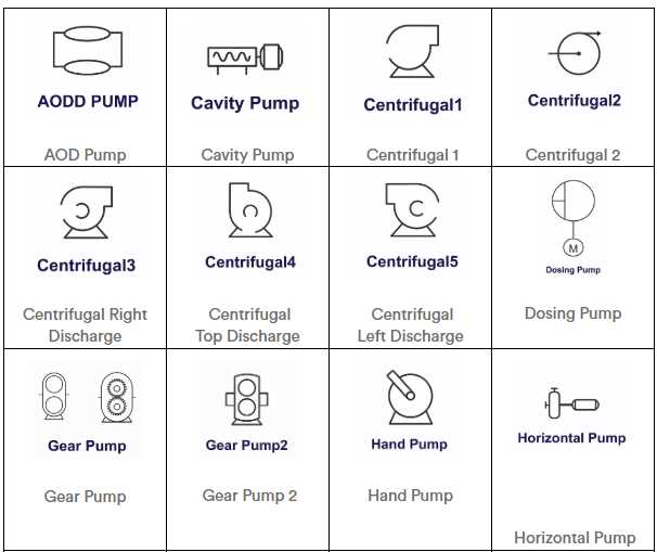
A vacuum pump is an essential component in many industrial and scientific processes. It is used to remove gas molecules from a sealed volume, creating a vacuum or low-pressure environment. The schematic symbol for a vacuum pump represents its function and operation in a simplified and standardized way, allowing engineers and technicians to easily understand and identify the component.
The schematic symbol for a vacuum pump typically consists of two main elements: a triangle and a circle. The triangle represents the suction or intake side of the pump, where gas molecules are drawn in. The circle represents the exhaust or outlet side of the pump, where the gas molecules are expelled. These two elements are connected by a line or an arrow, indicating the flow of gas through the pump.
In addition to the triangle and circle, the schematic symbol for a vacuum pump may also include other elements to provide more specific information about its type, size, or operation. For example, a rotary vane pump, which is a common type of vacuum pump, may have additional lines or shapes to indicate the rotating mechanism and the vanes inside the pump.
Overall, the schematic symbol for a vacuum pump is a simple yet powerful tool for engineers and technicians. It allows them to quickly identify and understand the function and operation of the pump, enabling them to effectively design and troubleshoot vacuum systems in various industries and applications.
What is a vacuum pump schematic symbol?
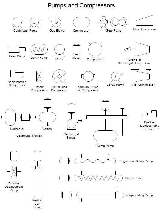
A vacuum pump schematic symbol is a graphical representation that is used to represent a vacuum pump in a schematic diagram. Schematic symbols are standardized icons or shapes that are used in circuit diagrams, process flow diagrams, and other technical drawings to represent different components and devices.
In the case of a vacuum pump, the schematic symbol typically consists of a circle with a diagonal line inside it, representing the pump’s housing or body, and an arrow pointing towards the circle, representing the direction of the flow of air or gas being pumped. The symbol may also include additional graphical elements or text to indicate specific features or specifications of the pump.
The use of schematic symbols allows engineers, technicians, and other professionals to quickly and easily identify and understand the different components and devices used in a system or process. Vacuum pump schematic symbols are used in a wide range of industries and applications, including HVAC systems, scientific instruments, manufacturing processes, and more.
It is important to note that schematic symbols are not universal and may vary slightly depending on the specific industry or standards being used. It is always best to refer to the appropriate standards or documentation when interpreting or creating schematic diagrams.
Importance of Vacuum Pump Schematic Symbols
The use of vacuum pumps is essential in various industries and applications, including manufacturing, research, medical, and aerospace. These pumps are designed to create and maintain a vacuum within a system, allowing for the removal of gases or the creation of controlled environments. A vacuum pump schematic symbol is a graphical representation that represents the functioning and components of a vacuum pump, making it an indispensable tool for engineers, technicians, and anyone involved in designing or working with vacuum systems.
Clear Communication: Vacuum pump schematic symbols serve as a standardized way of communicating the operation and functionality of a vacuum pump system. By using these symbols, engineers and technicians can effectively convey complex ideas and designs in a concise and universally understood manner. This allows for better collaboration between different teams or individuals working on a project, ensuring that everyone is on the same page and understands the specifications of the vacuum system.
Design and Planning: Vacuum pump schematic symbols play a crucial role in the design and planning stages of any vacuum system. Engineers can easily incorporate these symbols into their design drawings or schematics to represent the various components and their connections accurately. This allows for efficient planning, identification of potential issues, and optimization of the system’s performance before the actual construction or implementation begins.
Troubleshooting and Maintenance: Vacuum pumps are complex machines with several components that require regular maintenance and troubleshooting. Vacuum pump schematic symbols provide a visual representation of these components, making it easier for technicians to identify and locate specific parts during maintenance or repair work. This aids in troubleshooting issues, expediting the repair process, and minimizing system downtime.
Training and Education: Vacuum pump schematic symbols are invaluable in training and educational settings. They help in teaching students and professionals about the principles of vacuum systems, the functionality of different components, and how they are connected. By familiarizing themselves with these symbols, individuals can gain a better understanding of how vacuum systems work and how to effectively design, operate, and maintain them.
Standardization: Standardized vacuum pump schematic symbols promote consistency and clarity across different industries and applications. These symbols ensure that engineers and technicians can easily understand and interpret drawings or schematics from various sources, regardless of their location or field of expertise. Standardization also simplifies the sharing of information and designs, making it easier to collaborate and innovate within the vacuum technology industry.
In conclusion, vacuum pump schematic symbols play a vital role in the design, communication, troubleshooting, and education related to vacuum systems. They enable engineers and technicians to effectively convey ideas, design accurate systems, and facilitate maintenance and repair work. The standardization provided by these symbols promotes collaboration and ensures consistent understanding across different industries and applications.
Common Vacuum Pump Schematic Symbols
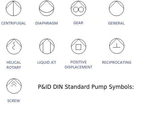
In mechanical and electrical schematics, vacuum pumps are often represented by specific symbols to indicate their function and operation. These symbols provide a concise visual representation of the vacuum pump and help engineers and technicians easily identify and understand its role within a system. Here are some common vacuum pump schematic symbols:
1. Single-stage Vacuum Pump Symbol:
The single-stage vacuum pump symbol typically consists of a circle with a horizontal line passing through the center. This symbol represents a basic vacuum pump with a single stage, where air or gas is evacuated through a single impeller or rotor.
2. Multi-stage Vacuum Pump Symbol:
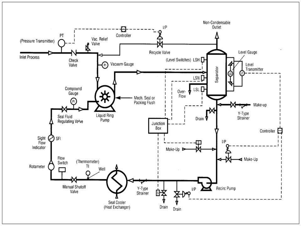
The multi-stage vacuum pump symbol is similar to the single-stage symbol but with additional horizontal lines passing through the circle. These horizontal lines indicate the presence of multiple stages or impellers in the vacuum pump, allowing for higher vacuum level achieved.
3. Rotary Vane Vacuum Pump Symbol:
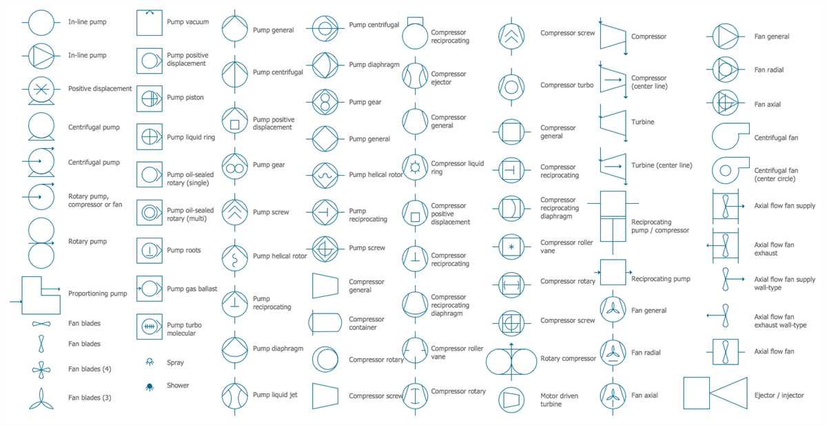
A rotary vane vacuum pump symbol looks like the single-stage vacuum pump symbol but with additional curved lines within the circle. These curved lines represent the vanes or blades inside the pump that rotate and create a vacuum by sealing off chambers and creating suction.
4. Diaphragm Vacuum Pump Symbol:
The diaphragm vacuum pump symbol is represented by a circle with a vertical line passing through the center and a curved horizontal line attached to it. This symbol depicts the diaphragm within the pump that moves up and down, creating a vacuum by compressing and expanding the working fluid.
5. Scroll Vacuum Pump Symbol:
A scroll vacuum pump symbol consists of two spiraling lines within a circle, with one line slightly offset from the other. This symbol represents a scroll vacuum pump where two scrolls or spirals within the pump create suction and evacuate the air or gas.
These are just a few examples of the common vacuum pump schematic symbols used in mechanical and electrical drawings. It is important to note that different industries and organizations may have variations or additional symbols specific to their applications. Therefore, it is always necessary to refer to the symbol key or legend provided in the schematic to ensure accurate interpretation and understanding.
Understanding the components of a vacuum pump schematic symbol
A vacuum pump is an essential component in many industrial processes and systems that require the creation or maintenance of a vacuum. To represent a vacuum pump in a schematic diagram, a specific symbol is used. Understanding the components of this schematic symbol can help in deciphering the function and operation of the vacuum pump.
The vacuum pump schematic symbol consists of various elements that represent the different parts and features of the pump. One of the key components is the rectangle, which represents the main body or casing of the pump. Inside the rectangle, there are usually several other symbols and lines that indicate the specific configuration and design of the pump.
- Rotary vane pump: A common type of vacuum pump, the rotary vane pump is often represented in the schematic symbol as a triangle with a curved line inside. The triangle represents the casing, while the curved line represents the rotating vanes inside the pump.
- Piston pump: Another type of vacuum pump, the piston pump is typically represented in the schematic symbol as a rectangle with a diagonal line inside. The rectangle represents the casing, while the diagonal line represents the piston movement.
- Turbomolecular pump: A high-speed pump used in applications requiring ultra-high vacuum levels, the turbomolecular pump is usually represented in the schematic symbol as two parallel lines with evenly spaced diagonal lines in between. The parallel lines represent the casing, while the diagonal lines represent the blades or rotors inside the pump.
In addition to these main components, the vacuum pump schematic symbol may also include other elements such as arrowheads, lines, and labels to indicate the direction of flow, connections, and control mechanisms. These additional symbols and lines help to provide more detailed information about the pump’s operation and function.
By understanding the components of a vacuum pump schematic symbol, engineers, technicians, and operators can effectively interpret and analyze schematic diagrams in various industrial applications. This knowledge can help in troubleshooting, maintenance, and design tasks, ensuring the efficient and reliable operation of vacuum systems.
How to read and interpret a vacuum pump schematic symbol
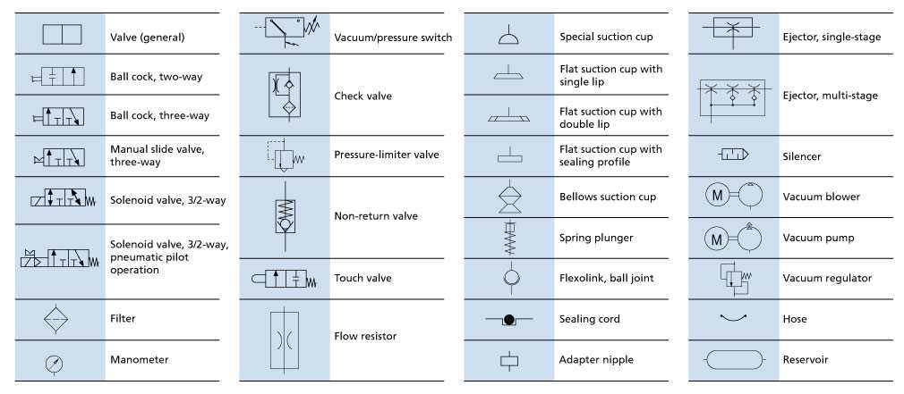
Reading and interpreting a vacuum pump schematic symbol is crucial for understanding the function and operation of vacuum systems. These symbols are commonly used in engineering drawings, diagrams, and schematics to represent various components and devices within a system.
The vacuum pump schematic symbol typically consists of a rectangular box with one or more arrows pointing into or out of it. The arrows indicate the direction of fluid flow, in this case, the movement of air or gas being evacuated from or pumped into the system. The number of arrows may vary depending on the specific pump configuration – a single arrow typically represents a single-stage pump, while multiple arrows indicate a multi-stage pump.
Furthermore, additional symbols, such as valves and pressure gauges, may be present in the same schematic to illustrate the complete vacuum system setup. These symbols provide essential information about the control and measurement points within the system. For example, a valve symbol may be positioned between the vacuum pump and the external environment, allowing the operator to control the flow of fluid into or out of the system.
Interpreting the vacuum pump schematic symbol involves understanding the overall system configuration and the role of the pump within it. By studying the schematic and analyzing the connections between various components, engineers and technicians can gain insights into how the vacuum pump operates and how it interacts with other elements of the system. This knowledge is essential for troubleshooting, maintenance, and designing efficient vacuum systems.
In summary, the vacuum pump schematic symbol is a visual representation used in engineering drawings to represent the vacuum pump and its role within a larger vacuum system. Understanding these symbols allows engineers and technicians to interpret the function and operation of the pump, enabling them to design, troubleshoot, and maintain vacuum systems effectively.
Applications of Vacuum Pump Schematic Symbols
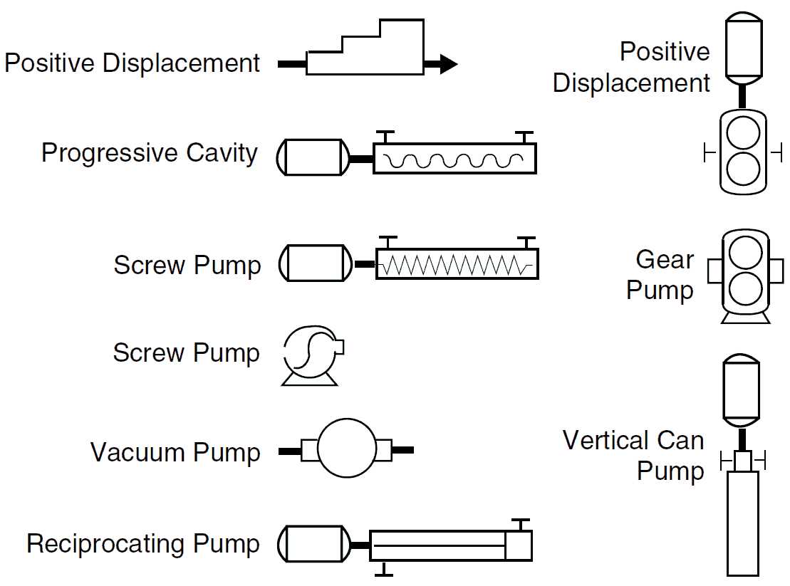
Vacuum pump schematic symbols find wide-ranging applications in various industries and disciplines. They are extensively used in engineering and design fields for representing and communicating vacuum pump systems in technical drawings, diagrams, and schematics. The symbols serve as a visual shorthand, making it easier for professionals to understand the concepts and designs related to vacuum pumps.
The applications of these symbols can be found in:
1. Mechanical Engineering
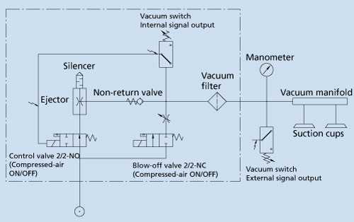
- System design: Vacuum pump schematic symbols are used to represent various types of vacuum pump systems, such as reciprocating pumps, rotary vane pumps, and liquid ring pumps. These symbols help mechanical engineers visualize and communicate their design ideas effectively.
- Assembly and maintenance: Vacuum pump schematic symbols are also used in assembly drawings and maintenance manuals to provide clear instructions for installing, operating, and maintaining vacuum pump systems.
2. HVAC (Heating, Ventilation, and Air Conditioning) Systems
- Ventilation systems: Vacuum pump schematic symbols are utilized to represent vacuum pumps used in ventilation systems for removing air and maintaining a controlled environment.
- Air conditioning systems: Vacuum pump schematic symbols help represent the vacuum pumps used in air conditioning systems for removing moisture and gases from the refrigeration circuits.
3. Laboratory and Scientific Applications
- Vacuum chambers: Vacuum pump schematic symbols are used to illustrate vacuum pumps used in laboratory experiments and scientific applications that require a controlled vacuum environment.
- Analytical instrumentation: Vacuum pumps are essential components in analytical instruments like mass spectrometers and electron microscopes. The use of vacuum pump schematic symbols helps in representing these instruments accurately.
4. Semiconductor Manufacturing
- Vacuum deposition systems: Vacuum pump schematic symbols are used in representing the vacuum pumps used in semiconductor manufacturing processes, such as chemical vapor deposition (CVD) and physical vapor deposition (PVD).
- Wafer processing: Vacuum pumps play a crucial role in various wafer processing steps like etching, ion implantation, and deposition. Vacuum pump schematic symbols are used in documentation related to these processes.
Summary
Vacuum pump schematic symbols have extensive applications in mechanical engineering, HVAC systems, laboratory and scientific applications, and semiconductor manufacturing. By using these symbols, professionals can effectively communicate, design, and analyze vacuum pump systems, ensuring efficient operation in various industries.