
A motor starter is an electrical device that is used to control the starting and stopping of an electric motor. It ensures that the motor starts and stops in a safe and controlled manner, preventing any damage or accidents. One common way to wire a motor starter is using the start-stop circuit diagram.
The start-stop circuit diagram consists of various components that work together to control the motor’s operation. These components include a power supply, a start button, a stop button, overload protection, and a contactor or relay. The power supply provides the necessary electric current to the motor, while the start and stop buttons control its operation.
When the start button is pressed, the circuit is completed, and the motor starts running. At the same time, the contactor or relay is energized, allowing the power supply to flow to the motor. Once the motor is running, the start button can be released. To stop the motor, the stop button is pressed. This breaks the circuit, de-energizes the contactor or relay, and cuts off the power supply to the motor, bringing it to a stop.
It is important to properly wire the motor starter using the start-stop circuit diagram to ensure the safe and efficient operation of the motor. Following the correct wiring diagram helps prevent any electrical issues or malfunctions, and it also allows for easy troubleshooting and maintenance of the motor starter system.
With the proper wiring diagram and installation, the motor starter can effectively control the starting and stopping of an electric motor, providing reliable and safe operation for various industrial and commercial applications.
The Basics of Motor Starter Wiring Diagram Start Stop
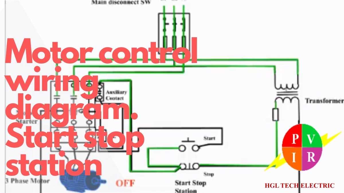
Motor starter wiring diagrams are essential in understanding the electrical connections and circuits involved in starting and stopping a motor. The start-stop control circuit is commonly used in industrial applications to control motor operation. This circuit provides a simple and efficient way to start and stop a motor, ensuring safe and efficient operation.
The motor starter wiring diagram start stop typically includes various components such as a power source, motor starter, control circuit, and start-stop buttons. The power source supplies the necessary voltage and current to the motor. The motor starter, also known as a contactor or relay, is responsible for controlling the flow of power to the motor. The control circuit connects the start and stop buttons to the motor starter, allowing the user to start and stop the motor as desired.
When the start button is pressed, it energizes the coil in the motor starter, which in turn closes the contacts and allows current to flow to the motor. The motor then starts running. When the stop button is pressed, it de-energizes the coil in the motor starter, causing the contacts to open and interrupting the current flow to the motor. This stops the motor from running.
It is important to properly wire the motor starter and control circuit to ensure reliable operation and prevent any potential electrical hazards. The wiring diagram provides a visual representation of how the various components are connected and the circuitry involved. This allows electricians and technicians to easily understand and troubleshoot any issues that may arise.
In conclusion, motor starter wiring diagram start stop provides a clear and concise way to understand the electrical connections and circuitry involved in starting and stopping a motor. By following the wiring diagram and properly connecting the components, users can ensure safe and efficient motor operation in industrial applications.
What is a Motor Starter?
A motor starter is an electrical device used to start and stop a motor. It is an important component in the operation and control of electric motors, providing a means to safely control the motor’s operation. Motor starters are commonly used in various industrial and commercial applications, such as manufacturing plants, HVAC systems, and pump controls.
The main function of a motor starter is to provide power to the motor and control its starting and stopping. It typically consists of a contactor, overload relays, and a control circuit. The contactor is an electromechanical switch that connects and disconnects the motor from the power source. The overload relays protect the motor from excessive current and prevent damage. The control circuit allows the operator to manually start and stop the motor using start and stop buttons.
Motor starters are designed to provide safe and reliable operation of motors. They are equipped with various safety features, such as thermal overload protection and short circuit protection, to prevent motor damage and electrical hazards. Motor starters also ensure smooth and controlled motor starts, reducing the risk of mechanical stress and equipment failure.
- Contactor: An electromechanical switch used to connect and disconnect the motor from the power source.
- Overload relays: Protection devices that prevent motor damage from excessive current.
- Control circuit: The circuit that allows the operator to start and stop the motor using control buttons.
- Safety features: Thermal overload protection and short circuit protection to prevent motor damage and electrical hazards.
In conclusion, a motor starter is an essential component in the control and operation of electric motors. It provides a safe and reliable means to start and stop motors, ensuring smooth operation and preventing damage. By incorporating various safety features, motor starters offer an added level of protection for both the motor and the operator.
Understanding the Start Stop Circuit
The start stop circuit is an essential component of motor starter wiring diagrams. It is a control circuit that allows the user to start and stop the motor by pressing corresponding buttons. This circuit is commonly used in industrial and commercial applications, where the motor needs to be controlled remotely.
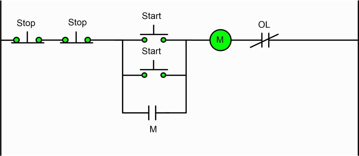
Start Button: The start button is a momentary switch that is normally open. When it is pressed, it completes the circuit, allowing current to flow to the motor. This energizes the motor’s starter coil, which in turn energizes the motor’s main contactor, allowing power to reach the motor and start it.
Stop Button: The stop button is also a momentary switch that is normally closed. When it is pressed, it breaks the circuit, cutting off the power supply to the motor. This de-energizes the motor’s starter coil and main contactor, stopping the motor’s operation.
The start and stop buttons are connected in parallel to the control circuit. This means that pressing either one of the buttons will have the same effect on the motor’s operation. If the start button is pressed, the motor will start. If the stop button is pressed, the motor will stop.
The start and stop circuit also includes other components, such as overload relays and interlocks, to protect the motor and ensure safe operation. Overload relays are used to protect the motor from overheating by monitoring the current flowing to the motor. Interlocks are used to prevent the motor from starting or stopping under certain conditions, such as when safety doors are open or when the motor is already running.
In summary, the start stop circuit is a vital part of motor starter wiring diagrams. It allows for remote control of the motor’s operation by using momentary start and stop buttons. It is important to understand and properly wire this circuit to ensure safe and efficient motor operation.
Wiring Diagram for Motor Starter Start Stop Circuit
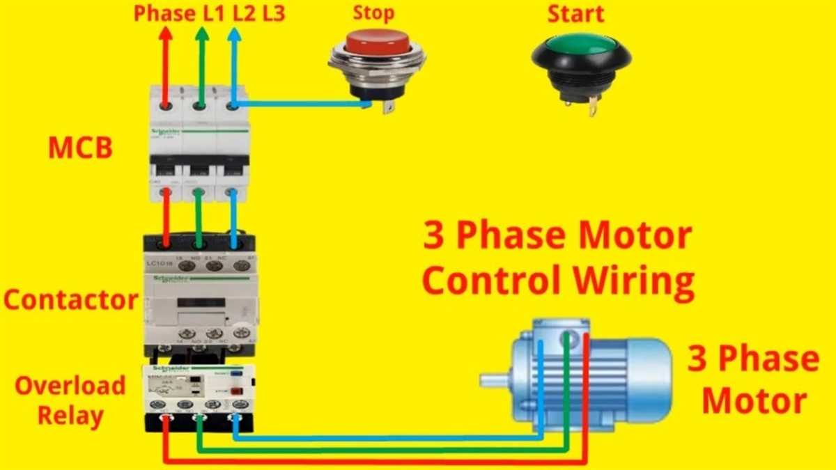
In an industrial setting, it is common to use motor starters to control the operation of electric motors. The motor starter is responsible for controlling the flow of electrical power to the motor, ensuring safe and efficient operation. One common motor starter configuration is the start-stop circuit, which allows for manual control over the motor’s start and stop functions.
The wiring diagram for a motor starter start-stop circuit typically consists of several components. These include a power source, such as a circuit breaker or fuse, to provide electrical power to the starter. There is also a start button and stop button, which are used to manually control the start and stop functions of the motor. Additionally, the motor starter itself is included in the circuit, typically shown as a rectangle with various connection points.
The wiring diagram will indicate the connections between these components:
- The power source is connected to the input side of the motor starter, usually through a protective device like a fuse or circuit breaker.
- The start button is connected to a control terminal on the motor starter, typically marked with the letter “S”.
- The stop button is connected to another control terminal on the motor starter, usually marked with the letter “T”.
- The motor itself is connected to the output side of the motor starter, typically through a set of three wires for three-phase motors.
When the start button is pressed, the motor starter will energize and close its contacts, allowing electrical power to flow to the motor. This will cause the motor to start running. When the stop button is pressed, the motor starter will de-energize and open its contacts, cutting off power to the motor and causing it to stop.
The wiring diagram for a motor starter start-stop circuit is an essential tool for understanding the electrical connections and functions of the various components involved. It allows electricians and maintenance personnel to troubleshoot and repair any issues that may arise with the motor starter or associated wiring.
Common Mistakes to Avoid
In motor starter wiring diagrams for start-stop control circuits, there are several common mistakes that can easily be made. These mistakes can prevent the motor from starting or stopping properly, or even result in damage to the equipment. It’s important to be aware of these mistakes and take steps to avoid them.
1. Incorrect wiring connections: One common mistake is making incorrect wiring connections. This can happen when wires are not properly labeled or when the diagram is not followed correctly. It’s important to carefully study the diagram and double-check all connections before powering the system.
2. Overloading the starter: Another mistake to avoid is overloading the motor starter. Motor starters have specific current ratings, and exceeding this rating can cause damage to the starter or even result in a circuit overload. It’s important to check the motor’s current requirements and select a starter that is rated accordingly.
3. Lack of proper safety precautions: Safety is always a priority when working with electrical systems. One common mistake is failing to take proper safety precautions when wiring the motor starter. This can include not wearing appropriate protective gear, not de-energizing the system before working on it, or not properly grounding the equipment. It’s important to always follow safety guidelines and use the proper safety equipment.
4. Ignoring motor starter size: Motor starters come in different sizes to accommodate different motor sizes and load requirements. It’s important to select the correct size motor starter for the specific application. Using an undersized starter can result in overheating and premature failure, while using an oversized starter can lead to unnecessary costs and inefficient operation.
5. Poor wire management: Finally, poor wire management can lead to problems in motor starter wiring. This includes issues such as improper wire routing, inadequate wire sizes, or using incorrect wire types. It’s important to carefully plan the wire routing and select the proper wire sizes and types to ensure reliable operation of the motor starter.
By being aware of these common mistakes and taking steps to avoid them, you can ensure a properly functioning motor starter wiring diagram for start-stop control circuits. It’s important to follow the manufacturer’s guidelines and consult with a qualified electrician if needed. Proper installation and maintenance will help prevent issues and ensure the longevity of the equipment.
Troubleshooting Motor Starter Wiring Issues
Motor starter wiring issues can be frustrating and can result in your motor not starting or stopping properly. However, by following a systematic troubleshooting approach, you can identify and resolve these wiring problems effectively. Here are some common issues you may encounter and how to troubleshoot them:
Incomplete Circuit:
If your motor is not starting or stopping, one possibility is that there is an incomplete circuit somewhere in the wiring. Start by checking all connections and ensure that they are secure. Look for loose or damaged wires, and fix or replace them as necessary. Additionally, verify that the power supply is active and providing the correct voltage.
Incorrect Wiring Connections:
Another common problem is incorrect wiring connections. Double-check all wiring connections against the motor starter wiring diagram to ensure they are properly connected. Pay close attention to the configuration of the start and stop push buttons, as well as any interlocks or auxiliary contacts.
Faulty Starter Components:
If the wiring connections are correct, but the motor still does not start or stop correctly, the issue may lie with faulty starter components. Check the overload relay, contactor, and any other components for damage or malfunction. Replace any defective parts to restore proper function. It may be helpful to consult the motor starter manufacturer’s documentation for troubleshooting guidance specific to your model.
Overload Tripping:
If the motor starter trips the overload relay frequently, it may indicate an issue with the motor or the load it is driving. Evaluate the load and verify that it is within the motor’s rated capacity. Additionally, check the motor for any mechanical issues that could be causing excessive current draw or overheating. Clean or lubricate the motor if necessary, or consult a qualified technician for further assistance.
Remember to always prioritize safety when troubleshooting motor starter wiring issues. Disconnect the power supply and follow appropriate safety procedures before working on any electrical equipment. If you are unsure or uncomfortable with troubleshooting electrical systems, it is best to seek the assistance of a qualified electrician or technician.