
When it comes to measuring pressure in industrial applications, the 4-20mA pressure transducer is one of the most widely used instruments. This transducer offers reliable and accurate pressure readings, making it an essential component in various industries such as oil and gas, manufacturing, and automotive.
Understanding the wiring diagram of a 4-20mA pressure transducer is crucial for proper installation and operation. In this article, we will provide a comprehensive guide on how to wire a 4-20mA pressure transducer, including the necessary components, steps, and precautions.
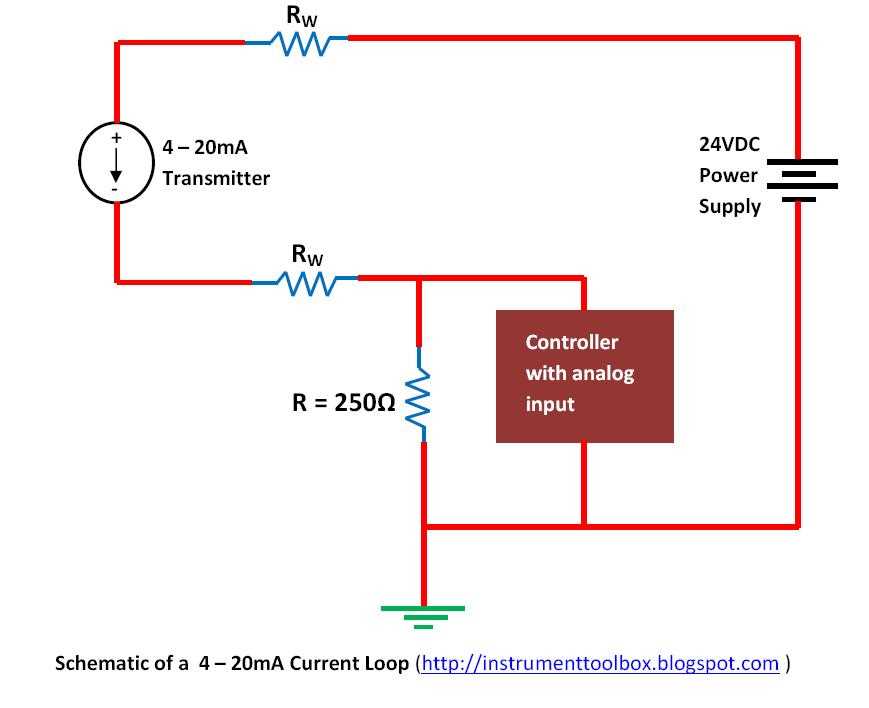
A 4-20mA pressure transducer operates on a current-loop system, where the pressure reading is represented by the current output. A 4mA current corresponds to the lowest pressure, while a 20mA current represents the highest pressure. By connecting the transducer to a suitable power supply and an analog input device, you can obtain accurate pressure readings in real-time.
When wiring a 4-20mA pressure transducer, it is essential to follow the manufacturer’s instructions and consider safety precautions. Incorrect wiring or inadequate grounding can lead to inaccurate readings, equipment damage, or even electrical hazards. By understanding the wiring diagram and following the right procedures, you can ensure a successful installation and reliable pressure measurements.
Understanding the Wiring Diagram of a 4-20mA Pressure Transducer
A 4-20mA pressure transducer is a device used to measure pressure in various industrial applications. It is commonly used in systems where accurate and reliable pressure measurements are required. Understanding the wiring diagram of a 4-20mA pressure transducer is essential for proper installation and integration into a system.
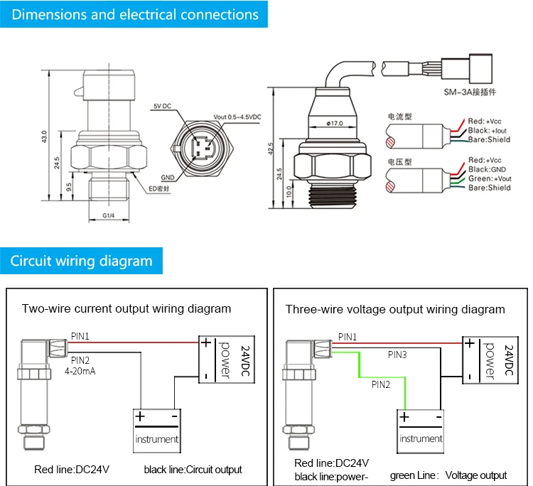
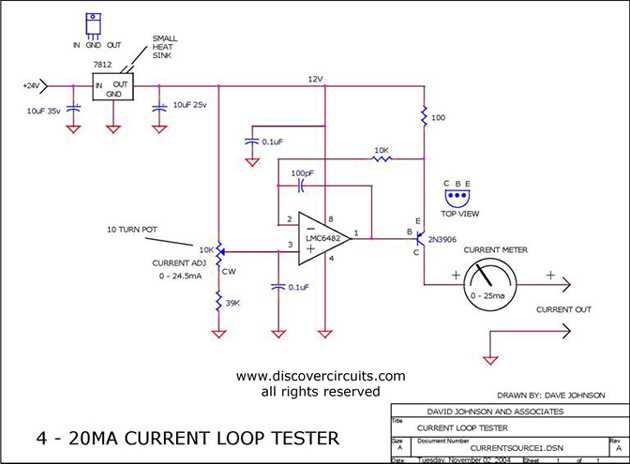
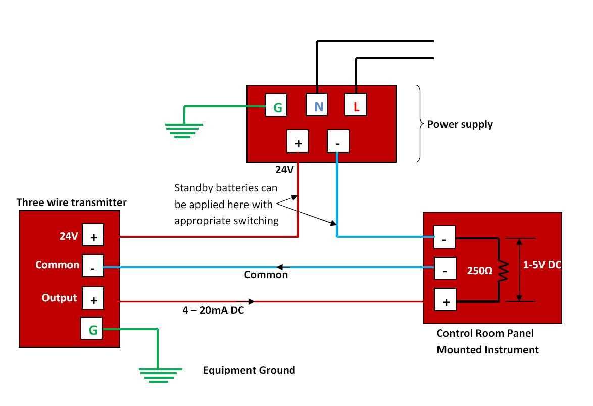
The wiring diagram of a 4-20mA pressure transducer typically includes four terminals: +V, GND, OUT, and REF. These terminals are used to connect the transducer to the power supply and the receiving device.
- +V: The +V terminal is connected to the positive side of the power supply. It provides the required voltage for the operation of the transducer.
- GND: The GND terminal is connected to the ground or negative side of the power supply. It serves as the reference point for the transducer.
- OUT: The OUT terminal is the output of the transducer, which provides the 4-20mA current signal proportional to the measured pressure. This signal can be connected to a controller, data acquisition system, or other devices for further processing.
- REF: The REF terminal is used to connect an external reference voltage to improve the accuracy and stability of the transducer’s output signal. It is optional and may not be present in all models of pressure transducers.
It is important to follow the wiring diagram provided by the manufacturer of the pressure transducer. Incorrect wiring can lead to inaccurate measurements or damage to the transducer and other system components.
Additionally, proper signal conditioning may be required to convert the 4-20mA current signal to a voltage signal or to provide isolation and protection against electrical noise. This can be achieved using signal conditioners or transmitters, which are commonly available in industrial settings.
In conclusion, understanding the wiring diagram of a 4-20mA pressure transducer is crucial for successful installation and integration into a system. By correctly wiring the transducer’s terminals and providing the necessary signal conditioning, accurate and reliable pressure measurements can be obtained for various industrial applications.
What is a 4-20mA Pressure Transducer?
A 4-20mA pressure transducer is a type of sensor that is used to measure pressure and convert it into an electrical current signal. It is commonly used in various industrial applications where accurate and reliable pressure measurements are required.
The 4-20mA signal represents the pressure measurement range, with 4mA typically indicating the lowest pressure value and 20mA representing the highest pressure value. This current signal is proportional to the measured pressure and allows for easy transmission of the pressure data over long distances without significant loss or distortion.
How does a 4-20mA Pressure Transducer work?
A 4-20mA pressure transducer consists of a pressure sensing element, signal conditioning circuitry, and an output stage that generates the 4-20mA current signal. The pressure sensing element, often a strain gauge or piezoelectric sensor, detects the applied pressure and converts it into a corresponding electrical signal.
This electrical signal is then amplified and conditioned by the signal conditioning circuitry to ensure accuracy and stability. The output stage of the transducer converts the conditioned signal into the desired 4-20mA current signal, which can be easily interpreted and utilized by other system components or control devices.
Benefits of using a 4-20mA Pressure Transducer:
- Precision and accuracy: 4-20mA pressure transducers offer high precision and accuracy in measuring pressure, making them ideal for applications requiring precise pressure control.
- Long transmission distances: The 4-20mA current signal is capable of traveling long distances without experiencing significant signal loss or interference, making it a reliable choice for remote pressure monitoring.
- No external power supply needed: The 4-20mA current loop does not require an external power supply, as it is powered by the receiving device. This simplifies installation and reduces the overall system complexity.
- Easy integration: 4-20mA pressure transducers can be easily integrated into various industrial control systems and microprocessor-based devices due to their standardized current signal.
In conclusion, a 4-20mA pressure transducer is a versatile and reliable sensor used for measuring pressure in industrial applications. Its ability to provide accurate and stable pressure measurements, long-distance transmission capabilities, and compatibility with various control systems make it a popular choice for pressure monitoring and control.
Importance of Proper Wiring
Proper wiring is essential when it comes to the installation and operation of a 4 20mA pressure transducer. The correct wiring ensures accurate and reliable transmission of the sensor’s output signal, allowing for precise measurement and monitoring of pressure levels.
One of the key reasons why proper wiring is important is to prevent signal interference and noise. Any unwanted electrical noise or interference can disrupt the signal from the transducer, leading to inaccurate readings and unreliable data. Properly insulated and shielded wiring helps to minimize these interferences, ensuring that the transducer’s output signal remains stable and consistent.
Additionally, proper wiring also ensures electrical safety. A 4 20mA pressure transducer is typically connected to a power source, and any improper wiring can lead to electrical hazards, such as short circuits or electrical fires. By following the recommended wiring diagrams and using the appropriate wire sizes and connectors, the risk of electrical accidents can be significantly reduced.
Furthermore, proper wiring simplifies troubleshooting and maintenance. When the wiring is done correctly, it is easier to identify and diagnose any issues that may arise with the transducer or its connections. This saves time and effort in locating the problem and allows for quick resolution to minimize downtime.
In conclusion, proper wiring is crucial for the successful operation of a 4 20mA pressure transducer. It ensures accurate measurements, prevents signal interference, promotes electrical safety, and simplifies maintenance procedures. By following the recommended wiring guidelines, users can optimize the performance and reliability of their pressure monitoring systems.
Wiring Diagram Overview
In the field of industrial automation and process control, pressure transducers play a crucial role in measuring and monitoring pressure levels. These transducers convert the applied pressure into an electrical signal, typically a 4-20mA current loop, which is then used by various devices and systems for control and analysis purposes.
A wiring diagram is a visual representation of the connections and components involved in the wiring of a pressure transducer. It provides an overview of how the transducer is connected to the rest of the circuit or system, facilitating troubleshooting and maintenance. Understanding the wiring diagram is essential for proper installation and operation of the pressure transducer.
The wiring diagram for a 4-20mA pressure transducer typically includes the following components and connections:
- Power supply: The power supply provides the necessary voltage for the operation of the pressure transducer. It is usually a DC power source.
- Signal conditioning circuit: The signal conditioning circuit is responsible for converting the electrical signal from the pressure transducer into a standardized 4-20mA current loop. It may include amplifiers, filters, and other components to ensure accurate measurement and transmission of the pressure readings.
- Transducer connections: The wiring diagram shows the necessary connections for the pressure transducer, including the positive and negative terminals for the power supply and the input/output terminals for the 4-20mA current loop.
- Device connections: The diagram also indicates the connections to other devices or systems that utilize the pressure readings, such as controllers, data acquisition systems, or displays.
By referring to the wiring diagram, technicians and engineers can identify any potential wiring issues, such as incorrect polarity or faulty connections, and troubleshoot them accordingly. It also serves as a reference for future maintenance or modifications to the pressure transducer wiring.
Overall, the wiring diagram provides a comprehensive overview of the electrical connections and components involved in the operation of a 4-20mA pressure transducer. It is an essential tool for ensuring proper installation, accurate measurement, and reliable performance of the transducer in industrial applications.
Step-by-Step Wiring Instructions
To properly wire a 4-20mA pressure transducer, follow these step-by-step instructions:
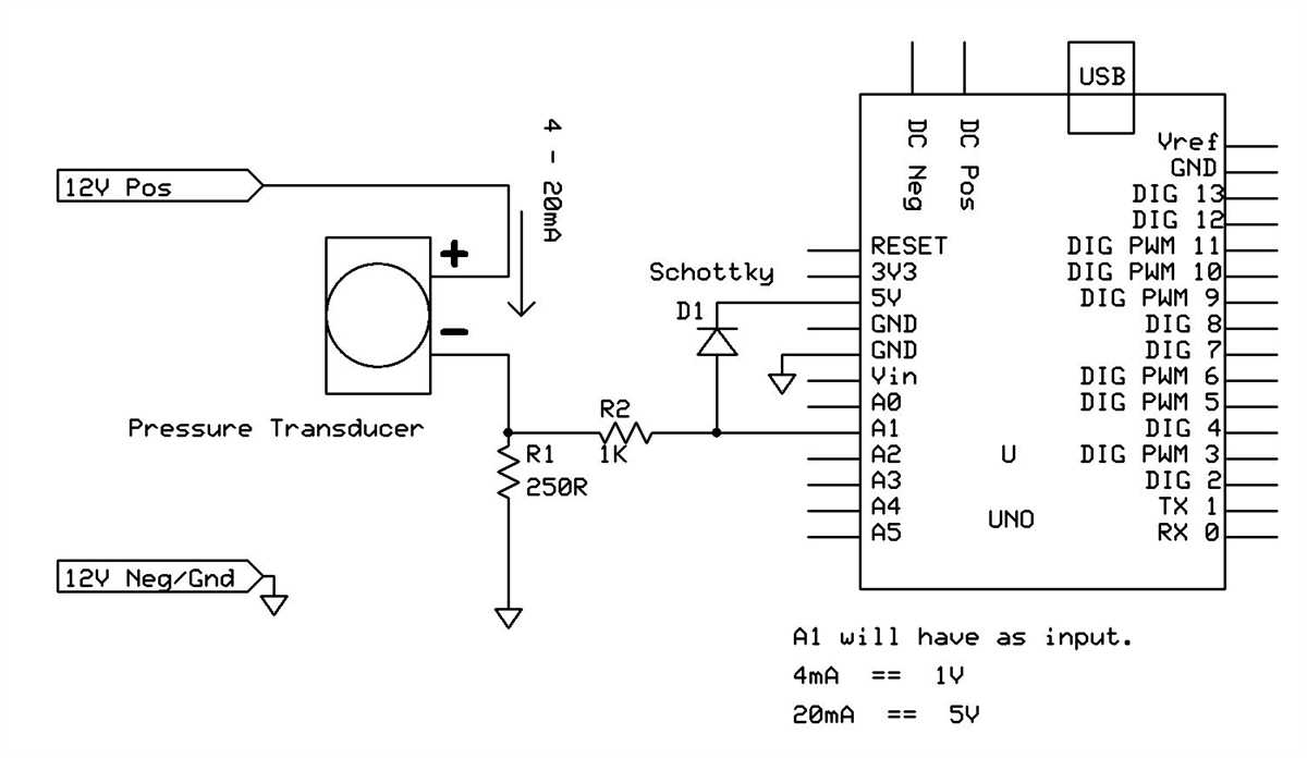
Step 1: Start by gathering the necessary tools and materials. You will need the pressure transducer, a power supply, an analog input module, and appropriate cables and connectors.
Step 2: Make sure to carefully read the datasheet and instructions provided by the manufacturer for the specific transducer you are working with. This will provide important details about the wiring process and any special considerations.
Step 3: Connect the power supply’s positive (+) terminal to the transducer’s positive terminal. This is typically labeled “V+” or “Vcc”. Use a suitable cable or connector to make a secure connection.
Step 4: Connect the power supply’s negative (-) terminal to the transducer’s negative terminal. This is usually labeled “GND” or “V-“. Again, ensure a proper and secure connection.
Step 5: Connect the analog input module’s positive (+) terminal to the transducer’s signal terminal. This is typically labeled “OUT” or “SIGNAL”. Use the appropriate cable or connector to establish a reliable connection.
Step 6: Connect the analog input module’s negative (-) terminal to the transducer’s negative terminal. This is usually labeled “GND” or “V-“. Double-check that the connection is secure.
Step 7: If required, connect any additional wires or terminals for features such as temperature compensation or additional outputs. Refer to the manufacturer’s instructions for guidance on any additional wiring.
Step 8: Once all the connections are made, double-check that all connections are secure and properly insulated. Ensure that there are no loose or exposed wires that could cause a short circuit.
By following these step-by-step wiring instructions, you can successfully wire a 4-20mA pressure transducer. Remember to always consult the manufacturer’s instructions and datasheet for specific guidance on the transducer you are working with.
Troubleshooting Common Wiring Issues

Proper wiring is crucial for the accurate operation of a 4-20mA pressure transducer. However, there are some common wiring issues that can occur, leading to problems with the transducer’s performance. Here are some troubleshooting tips to help you identify and resolve these issues:
1. Incorrect polarity
One of the most common wiring mistakes is connecting the power supply and the signal wires with the incorrect polarity. This can result in inaccurate readings or even damage to the transducer. Always double-check the wiring connections and make sure that the positive and negative terminals are correctly aligned.
2. Loose or damaged connections
Loose or damaged connections can create resistance, which can interfere with the proper transmission of the signal. Inspect all wire connections and ensure that they are tight and secure. If you notice any damaged wires or connectors, replace them immediately.
3. Incorrect wiring scheme
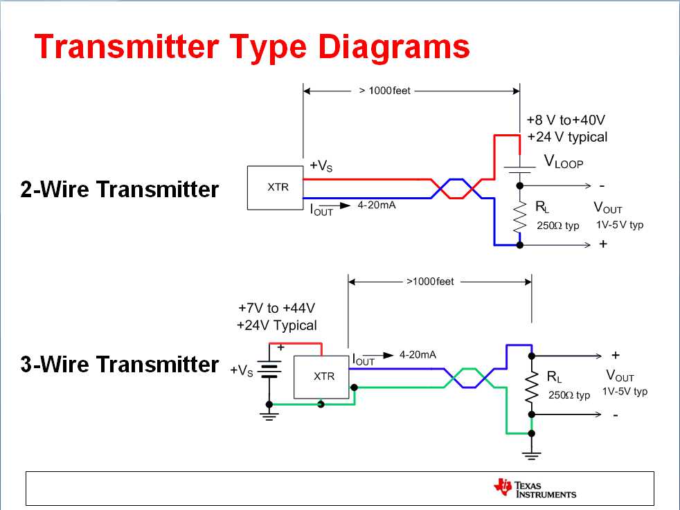
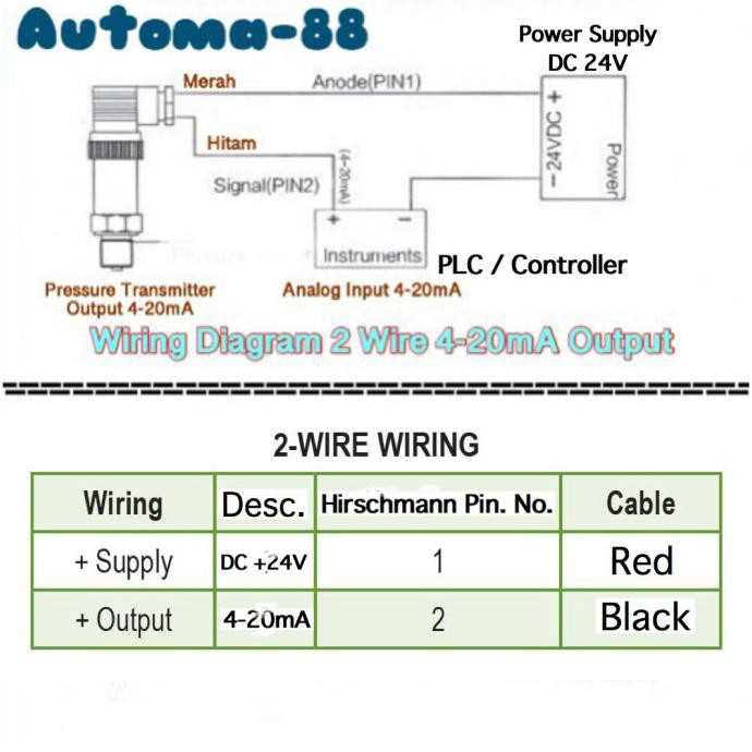
Another common issue is using the wrong wiring scheme. The most common scheme for a 4-20mA pressure transducer is two-wire, where both power supply and signal are transmitted through the same pair of wires. However, some transducers may require a three- or four-wire configuration. Check the manufacturer’s documentation to confirm the correct wiring scheme for your specific transducer.
4. Grounding issues
Improper grounding can introduce electrical noise and interfere with the transducer’s performance. Make sure that the transducer’s ground wire is properly connected to a clean and secure ground point. Avoid grounding it to sources of electrical noise, such as motor wiring or power converters.
5. Power supply voltage fluctuations
Voltage fluctuations in the power supply can affect the performance of the transducer. Check the power supply voltage using a multimeter and ensure that it falls within the specified range. If you notice any fluctuations, consider using a voltage regulator or stabilizer to maintain a consistent power supply.
By following these troubleshooting tips, you can effectively identify and resolve common wiring issues with your 4-20mA pressure transducer. Remember to always consult the manufacturer’s documentation for specific wiring instructions and guidelines.