Does anyone here have any experiences with fdecu 5? I just bought I found a problem was with the generator. a clip on wire on L2 cane off. with that I also went by the diagram on top of the unit which indicates the same?.
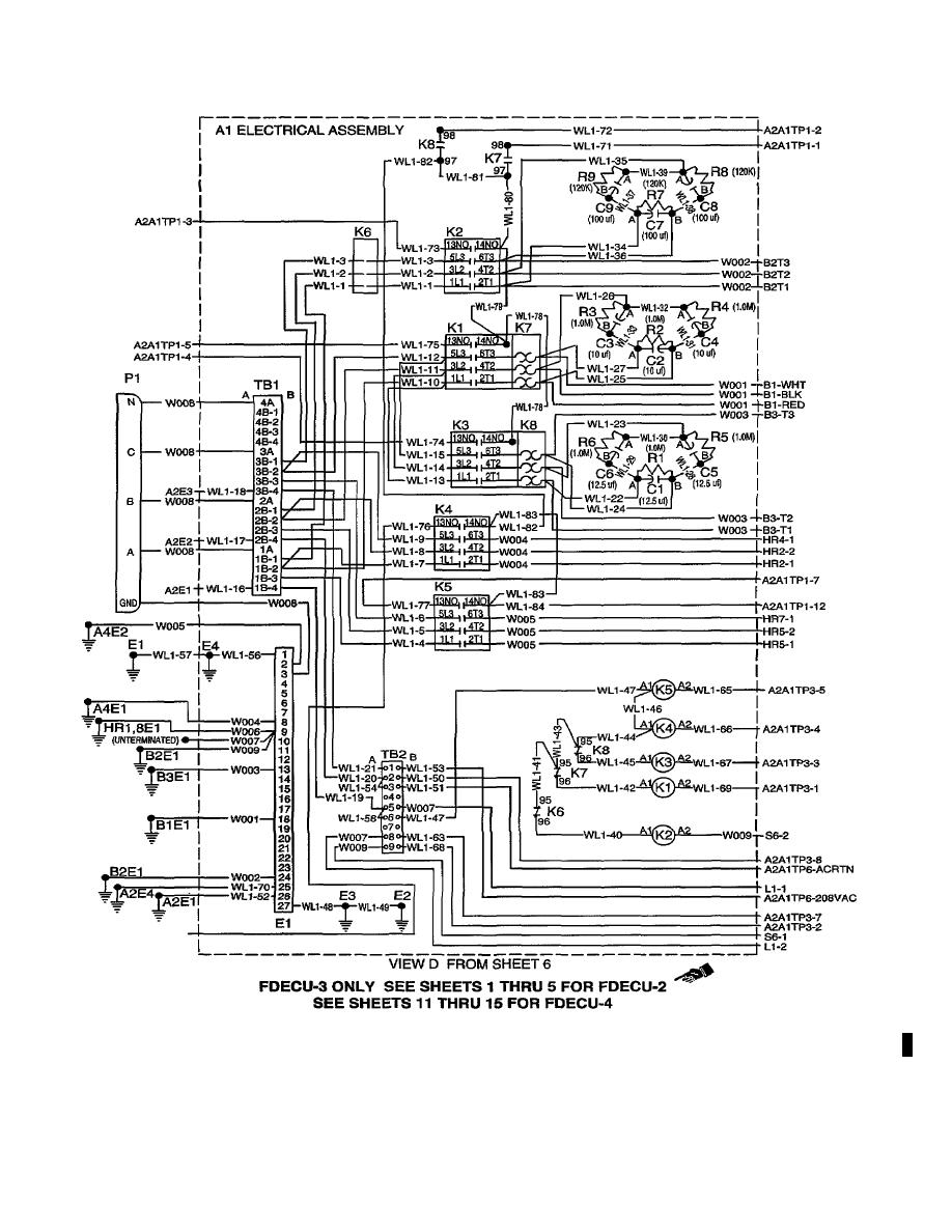
FDECUTM and parts replacement · 44 . Fire extinguisher tags, safety wire, charging · 35 Electrical system wiring diagram · 61 · Electrical.
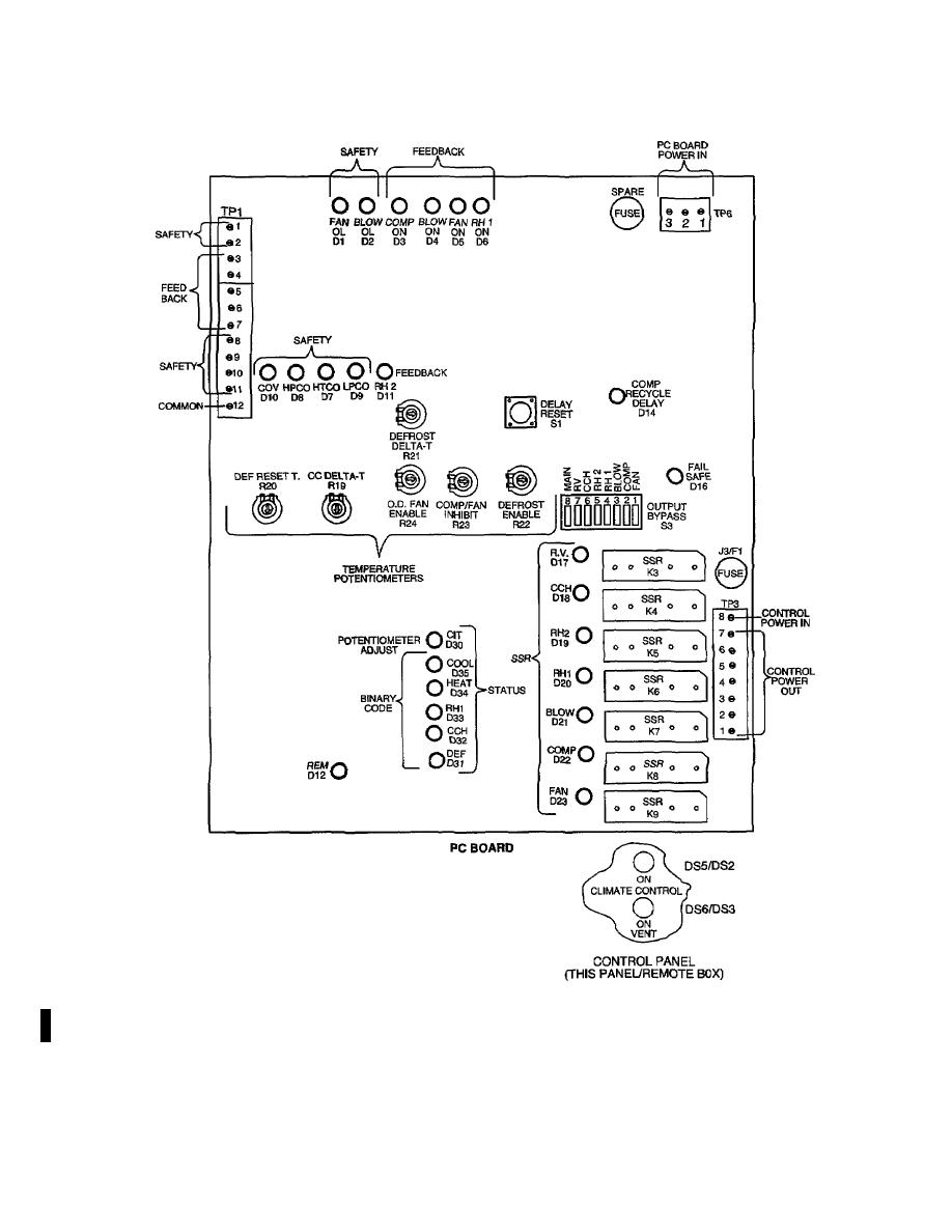
5. Typical Harvest Falcon Electrical Planning Factors .. equipment, such as the field deployable environmental control unit (FDECU), has a higher Identify where the SDCs will be located and mark the layout diagram.
TYPE I, GREEN, NSN: ELECTRICAL – electrical wire to arm with electricity symbol running through human body shows that shock FC. Female Connection.
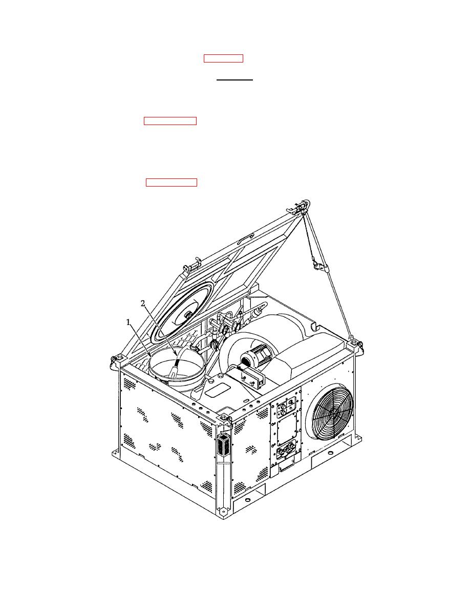
FDECU. Field Deployable Environmental Control.
Unit. FM Installation drawings, diagrams, instruction sheets, field.
Buy for others
(AFPAM) , Vol 5, Bare Base Conceptual Planning Guide, and in- struction received .. Power Supply Cable Connection to Refrigeration Unit ..
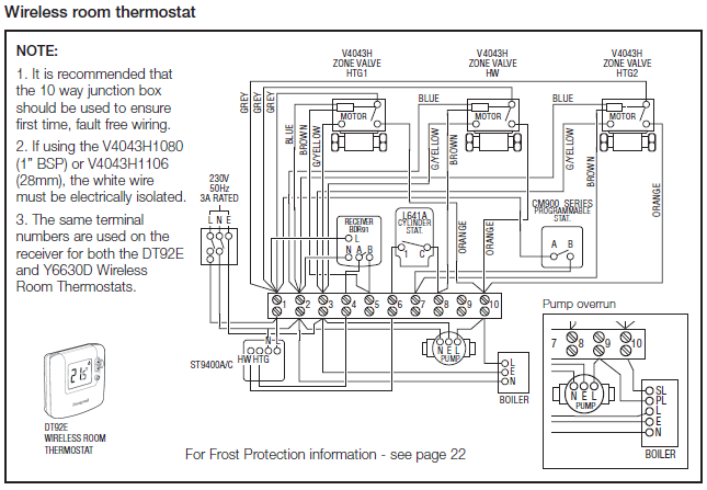
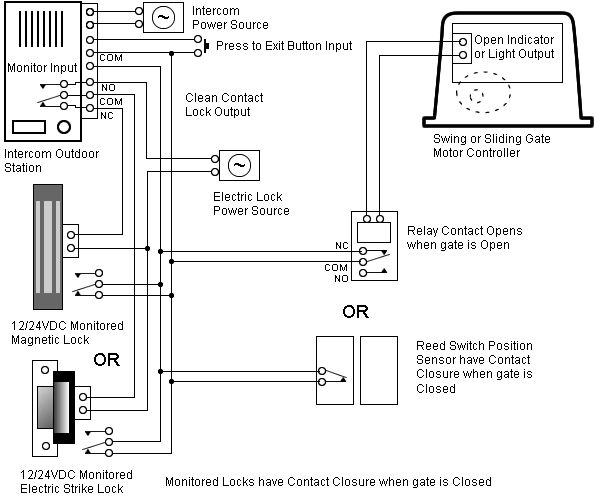
47 Field Deployable Environmental Control Unit (FDECU) wiring diagram from the schematic as was followed in the previous chapters Models Fdecu 2 Fdecu 3 And Fdecu 4 Nsn 01 ,Vw Golf Jetta Mk 2 Petrol 84 92 Haynes Service And Repair Manuals,Maimonides The Commandments Sefer Ha Mitzvoth The Mitzvoth Of . On this page are several wiring diagrams that can be used to map 3 way lighting circuits depending on the location of the source with relation to the lights.
Worlds Biggest Survival Ebooks and Military Manuals collection
Included is a diagram for a 3 way dimmer and an arrangement to for 3 way outlet control from two locations. Wiring Diagram (Sheet 3 of 5). Wiring Diagram (Sheet 5 of 5).
FM Transmitter with 5 compnents
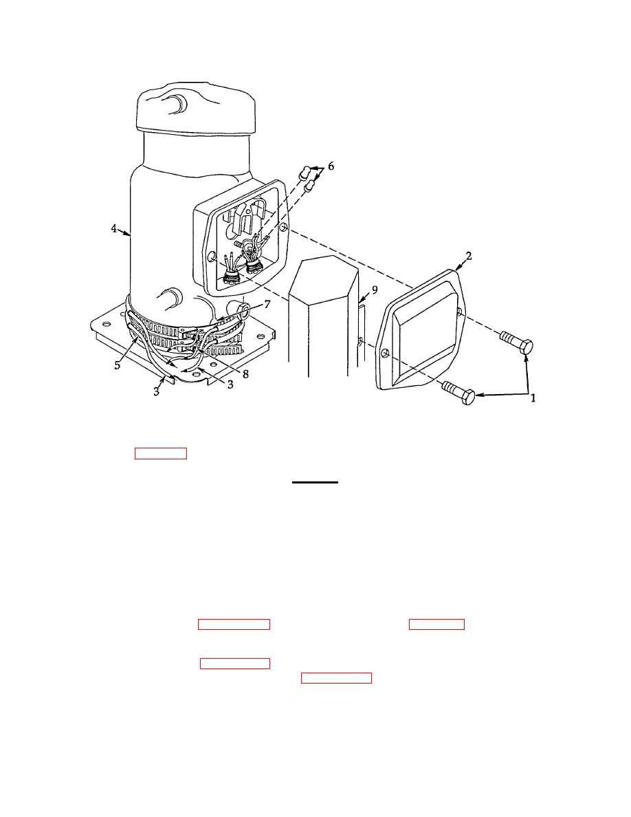
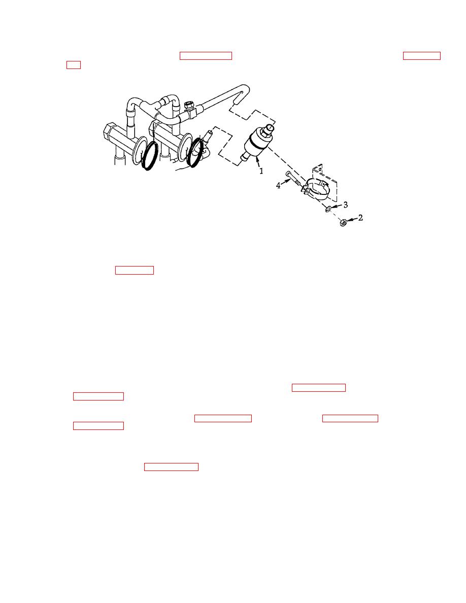
TM Field Deployable Environmental Control Unit Models FDECU-2 FDECU-3 and FDECU-4 . army technical manual tm air force technical manual t.o.

35e technical manual operator, unit, direct support and general support maintenance manual. wiring diagrams. Section 8W shows each connector and the circuits involved with that connector.
How To Wire RJ45 Cat 5 -5e – 6 ( Ethernet Cable Diagram Color Coding )
The connectors are identified using the name/number on the diagram pages. 8W – 01 – 8 8W WIRING DIAGRAM INFORMATION DR.AOP Commercial HVAC [Archive] – Page 58 – HVAC-Talk: Heating, Air & Refrigeration DiscussionFDECU – Field Deployable Environmental Control Unit | AcronymFinder
