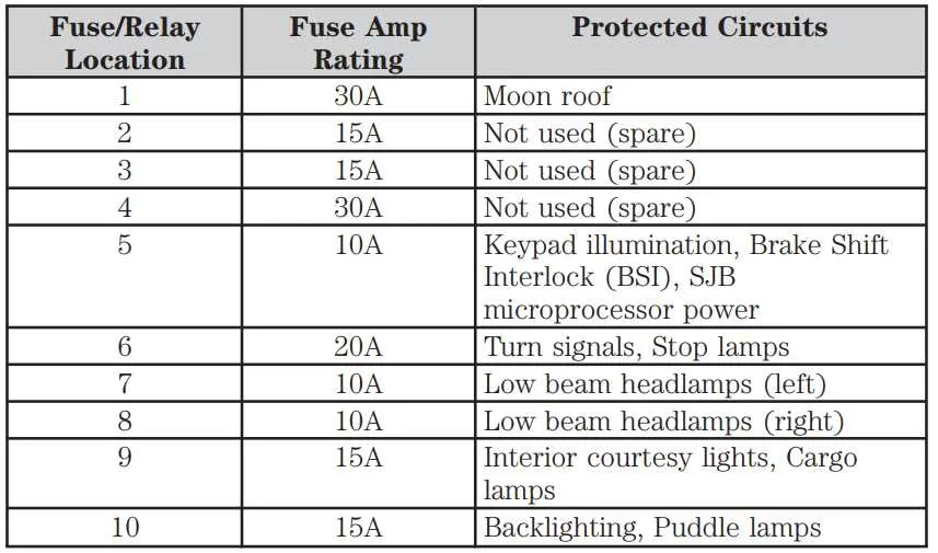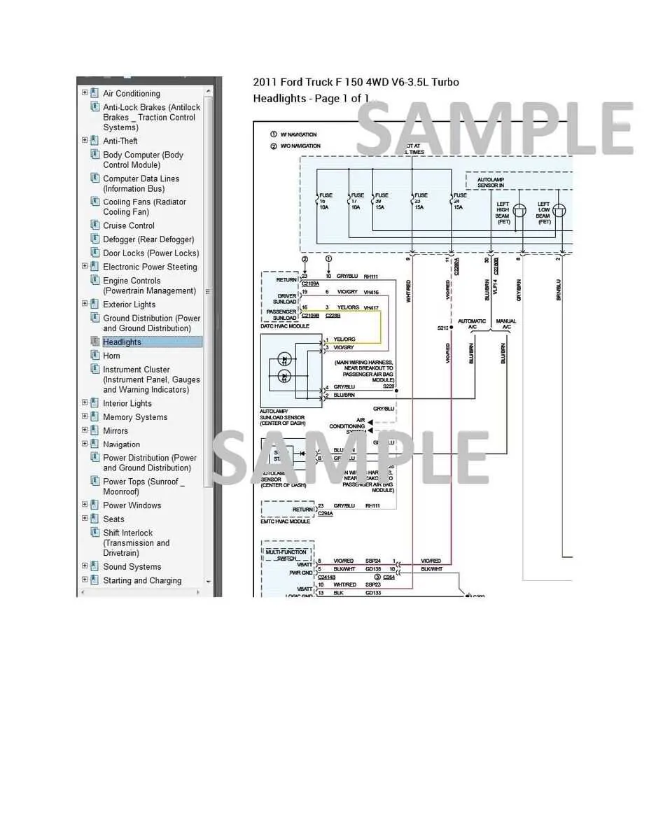
For proper troubleshooting and maintenance of your vehicle’s electrical system, having a clear reference to the arrangement of circuits and their respective locations is essential. Knowing where each fuse and relay is located within the system ensures quick fixes without unnecessary guesswork.
Start by consulting the vehicle’s service manual for a comprehensive breakdown of the fuse assignments. Each block is typically labeled, offering a straightforward way to identify which component controls specific features such as lighting, power windows, and even safety features like airbags.
If you’re dealing with a malfunction in a particular system, check the exact location of the corresponding relay and fuse. Consulting this reference will allow you to pinpoint the faulty circuit in no time, avoiding the need for costly repairs or part replacements.
For a more hands-on approach, use a diagram of the electrical layout to trace connections visually. This can speed up diagnostics by offering a clear map of where the problem might lie. Many resources are available online that provide detailed representations for various parts of the vehicle’s internal wiring.
By being familiar with this component setup, you not only save time but also reduce the risk of damage when working with the electrical system. Always double-check the ratings and locations of individual fuses to prevent issues from escalating.
Electrical System Component Layout
For effective troubleshooting, locate the central power distribution system, usually located under the driver’s side dashboard or within the engine compartment. It houses multiple relays and circuit protectors that manage essential systems, from the lighting to the ignition system.
Consult the vehicle’s owner manual for exact locations of each circuit, which can vary depending on the trim. For the cabin unit, check the array of connections near the footwell, which is often near the driver’s left knee. The engine bay unit, typically positioned near the battery, controls high-load functions like the AC or alternator circuits.
Ensure that any damaged links are promptly replaced with the recommended amperage. Overloaded circuits often cause system malfunctions, so using an incorrect fuse can lead to further electrical problems. Always refer to the vehicle’s official specification for the appropriate size and rating.
To prevent unintentional issues, verify the connections on each module. Make sure no corrosion or dirt obstructs the contact points. A clean, tight connection ensures the components function as intended and avoids unnecessary repairs.
In cases of electrical failure, inspect for any blown links in both compartments. If the fault persists after replacing components, consider consulting a professional for deeper diagnostics, as underlying wiring issues may be present.
Identifying Fuse Locations and Functions in the 2011 F150

To locate the correct slots for electrical protection devices in the vehicle, first, consult the owner’s manual for the exact layout of the electrical components. The primary locations for these protective elements are under the dashboard on the driver’s side and in the engine compartment near the battery.
Under-dash compartment: In this area, you’ll find devices responsible for interior lights, climate control, audio systems, and power windows. Check the labeling next to each holder to match the function with the corresponding location. Ensure the device controlling the lights and infotainment system is securely in place, as failure can result in a loss of power to both systems.
Engine compartment: This section controls major components such as the ignition system, headlights, and air conditioning. Focus on the larger protection units that manage the battery’s power supply and alternator. A common issue arises when these components lose power due to faulty connections or damaged protective units, so inspect for any irregularities carefully.
Tip: Always use the recommended amperage for replacement parts. An incorrect replacement may lead to electrical shorts or even a complete system failure. If uncertain, it’s always best to consult a professional to avoid costly repairs.
Common Fuse-Related Issues in the 2011 F150 and How to Fix Them

Start by checking the accessory delay relay (slot 27) if power windows or radio remain active after key removal. Replace the 10A micro blade component if continuity is broken.
- No Crank Condition: Inspect slot 27 and slot 33 (starter relay and ignition switch). A failed 20A cartridge unit often causes starting failure. Swap with a similar known-good part for testing.
- Non-Functional Trailer Lights: Evaluate position 67 and 68 in the rear junction block. A burned 20A module often results from wiring faults near the hitch connector. Use a test light to verify power presence.
- Blower Motor Not Working: Examine slot 13 under the hood. A faulty 40A J-case type disrupts HVAC performance. Ensure the blower motor relay (position 55) also functions.
- Power Outlet Failure: Look at cavity 22 inside the cab junction box. Replace the 20A yellow mini blade element. Use a voltmeter on the outlet terminals to confirm repair.
Always disconnect the battery before removal or installation. Use needle-nose pliers for tight sockets and verify amperage match to prevent overload. If replacements fail quickly, inspect for shorts or high-resistance connections in the relevant harness.
Step-by-Step Guide to Replacing Fuses in Your 2011 F150
Start by turning off the ignition and removing the key to prevent electrical shorts. Disconnect the negative battery terminal using a 10mm socket to eliminate power from the circuit.
Locate the interior access box beneath the steering column or the secondary unit under the hood near the battery. Use the diagram on the underside of the cover to identify the slot number corresponding to the affected system (e.g., headlights, blower motor, or power outlets).
Use needle-nose pliers or a plastic puller to remove the damaged component. A failed piece will typically show a visible break or discoloration in the U-shaped metal strip inside the translucent casing.
Match the replacement unit exactly by amperage rating (e.g., 10A red, 15A blue, 20A yellow). Inserting a unit with the wrong capacity can lead to system failure or even fire hazards.
Push the new piece firmly into place until it’s fully seated. Reconnect the battery terminal and test the previously nonfunctional circuit. If the issue persists, trace wiring or check related relays before repeating the swap.