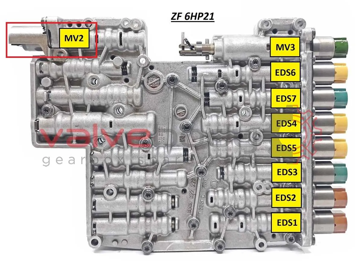
For effective troubleshooting and maintenance of the ZF six-speed automatic transmission, precise understanding of the yellow electrical valve’s layout in the second iteration is crucial. Accurate mapping of the actuator’s wiring paths allows technicians to pinpoint faults and optimize hydraulic control functions.
Focus on the connector terminals and wire colors when examining the circuitry related to this specific valve assembly. Each pin corresponds to a dedicated control or feedback signal, essential for the transmission’s shifting logic and pressure regulation.
Consult the revised schematic carefully to identify the updated routing and connections introduced in this version. Attention to the modified electrical paths ensures correct interpretation of sensor inputs and actuator outputs, preventing misdiagnosis and unnecessary component replacement.
Integrate this detailed layout with diagnostic tools to verify coil resistance, signal continuity, and operational response. Such a methodical approach guarantees enhanced reliability and precise control within the drivetrain system.
Detailed Wiring and Function Overview for ZF 6-Speed Valve Assembly
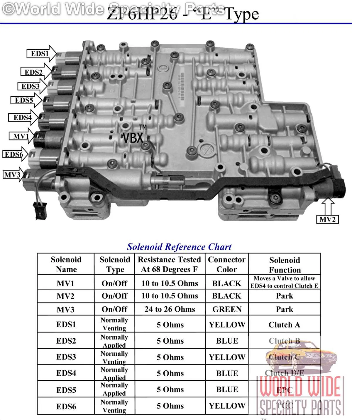
For accurate troubleshooting and repair, focus on the specific electrical paths and connector pin assignments related to the highlighted actuator coil in the second iteration of the ZF automatic transmission. The coil is controlled by the transmission control unit (TCU) via a dedicated circuit typically marked in wiring schematics with a distinct color code that separates it from other valve coils.
Pin configuration for this actuator includes a power supply line, ground, and signal return, which must be tested for continuity and voltage presence under operating conditions. Faults often arise from connector corrosion or wiring harness damage along the engine bay firewall.
Consult the service manual for the exact terminal numbers and expected resistance values to verify coil health. Resistance usually ranges between 20 and 30 ohms; deviations indicate a malfunction or short circuit.
During diagnostics, apply a direct 12V supply briefly to the coil to confirm its mechanical activation, ensuring the plunger moves freely without sticking. Failure to respond signifies internal coil failure or obstruction.
Integration with transmission control electronics demands precise timing of the coil activation. Erroneous wiring or connector misplacement causes improper gear shifts or limp mode engagement. Therefore, ensure proper routing of wiring harnesses and secure locking of connectors during assembly.
Identifying the Control Valve in ZF 6-Speed Transmission

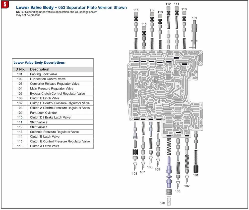
Locate the control valve by examining the transmission’s valve body. This component is typically a small, cylindrical element with a distinctive color, often marked for easy identification. It regulates fluid flow, enabling gear shifting based on electronic signals. You can find it in the section of the valve body where other similar components are clustered.
To identify the correct component, check its position relative to the other valves within the body. It usually sits near the central area of the valve body, often towards the rear. In some cases, it might be slightly recessed to avoid accidental displacement during maintenance.
When troubleshooting, verify the component’s condition by inspecting the connection points for any signs of wear or corrosion. These points should be clean and show no fluid leaks. A malfunctioning valve may cause irregular shifting patterns or a failure to shift at all, so ensuring it is properly seated and functional is essential for smooth operation.
Reading Electrical Connections on the Control Valve Wiring

To accurately interpret the electrical connections on the control valve, begin by identifying the key terminals on the wiring schematic. Start with the power input terminal; ensure it matches the required voltage for proper functionality. Next, locate the signal output connections, which are critical for receiving control commands from the system’s central processor. Make sure the ground connection is properly linked to avoid malfunctions caused by electrical surges or interference.
Verify the polarity of each wire using a multimeter to ensure correct orientation. The control signal typically flows through a set of resistors or capacitors; check for continuity to confirm no breaks or shorts in the circuit. Pay special attention to the voltage drop across components, as an unexpected reading may indicate a fault or resistance buildup.
If the system features a feedback loop, ensure the return signal is routed to the correct monitoring device. This will help in diagnosing errors and optimizing system performance. Double-check all connections before powering up the system to avoid potential damage or inaccurate operation.
Troubleshooting the Electrical Valve Using Wiring Plan

If the valve is not functioning properly, start by checking the power supply to the unit. Ensure that the battery voltage is sufficient and the fuse is intact.
Next, inspect the wiring connections for any signs of wear or loose contacts. Corroded or damaged wires can prevent proper functioning. Follow these steps for a systematic check:
- Verify that the wiring harness is securely connected to both the control module and the valve.
- Check for any frayed or exposed wires that could cause short circuits.
- Use a multimeter to test for continuity in the circuit. A lack of continuity indicates a broken or disconnected wire.
After confirming that the wiring is intact, check the electrical component’s resistance using the appropriate specifications from the reference manual. Deviations in resistance may indicate a faulty valve unit that needs replacing.
If all electrical connections are functional but the issue persists, inspect the signal input from the control system. A malfunction in the controller may be sending incorrect signals to the valve.
- Test the signal from the control unit using a diagnostic tool.
- If the signal is irregular, reset or reprogram the control system to restore normal operation.