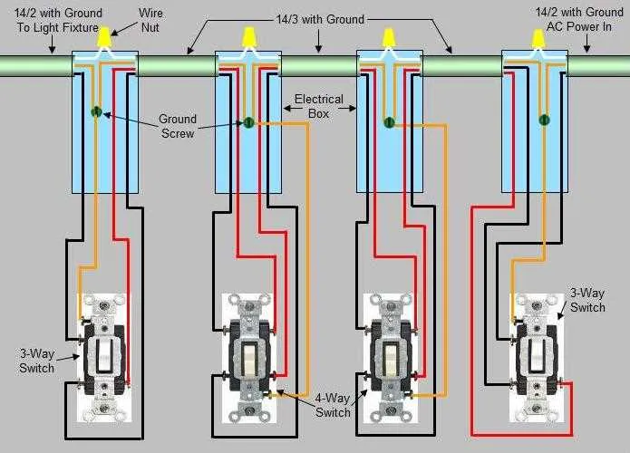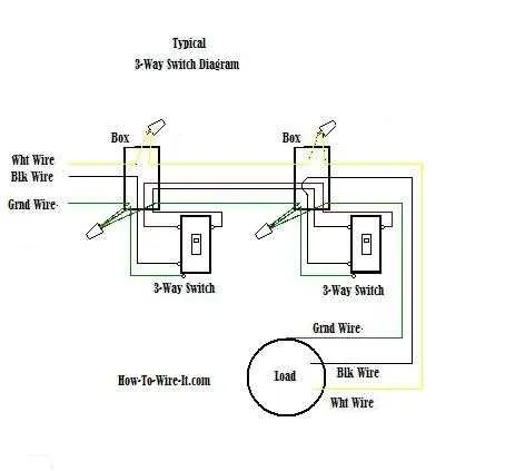
If you’re planning to control lighting from two separate locations, it’s essential to grasp the setup with four conductors. This configuration allows for precise management of lighting systems, offering flexibility and ease of use. A thorough understanding of how the components interact will help you achieve efficient installation and troubleshooting.
The key to a successful installation lies in properly connecting the traveler terminals and ensuring the correct orientation of each component. When you know the precise flow of current and the purpose of each conductor, the task becomes manageable. Always ensure that you adhere to standard color codes for safety and accuracy.
Tip: For smoother control, verify that your connections are solid and secure, preventing any potential disruptions in operation. This will contribute to longevity and consistent performance in your system.
Ensure safety protocols are followed during setup and never underestimate the importance of properly labeling each terminal. Incorrect wiring can lead to short circuits or system malfunction.
4 Wire 3-Way Circuit Configuration
For a proper installation of a multi-way control setup, ensure you use four conductors between two control points. This will allow for seamless operation of the light fixture from both ends. In this configuration, two conductors should carry the alternating current, while the other two manage the switching mechanism for the current path.
The first pair connects to the source of the electrical flow, typically at the main entry point. The second pair is responsible for transferring the control signals between the two terminal points, where the flow can be altered to either close or open the path to the light.
When configuring this setup, always check that the conductor connecting the control points is capable of handling the load. This ensures that the signal between points remains stable without compromising the system’s efficiency. To prevent electrical faults, use high-quality insulation to safeguard against short circuits and improper grounding.
Proper labeling of each conductor in the system is vital for future troubleshooting or modifications. Use clear markers to differentiate between the conductors managing current flow and the ones controlling the switching actions. This simple step will help reduce the chance of errors during installation or maintenance.
How to Connect a 4-Wire Circuit with Dual Control
To set up a four-wire dual control system, follow these steps to ensure proper functionality and safety:
- Power Source: Connect the incoming live cable to the common terminal of one of the devices.
- Traveler Connections: Use two separate traveler terminals to link the devices. One traveler wire goes from the first device to the second one. Ensure both are securely attached to their respective terminals.
- Grounding: Attach the ground wire to the metal box and the ground terminal of each unit. This prevents electrical hazards.
- Load Connections: On the second device, attach the outgoing cable to the common terminal, which will connect to the light or fixture being controlled.
- Testing: After completing the installation, test the system by toggling both devices to ensure that the light operates correctly from both locations.
Always use appropriately rated components and ensure compliance with local electrical codes. If unsure, consult a licensed electrician.
Identifying Common and Traveler Wires in a 4-Wire Setup

To correctly identify the common and traveler conductors in a 4-wire configuration, focus on the terminals where each conductor connects. The common conductor is typically linked to the terminal that remains fixed regardless of the position of the actuating device. This terminal is often marked differently or set apart from the others, providing a clear distinction.
The traveler conductors, on the other hand, connect to the remaining terminals. These will vary depending on the setting of the actuating mechanism, switching between positions. In many setups, travelers are often colored differently (e.g., red and black) to make identification easier during installation and troubleshooting.
Important Tip: The common conductor will generally have a direct connection to the power supply or the load, while the travelers connect between the two control points, allowing for the exchange of signals based on the position of the actuator.
Note: Verify connections using a voltage tester to ensure proper identification of each conductor before performing any work on the circuit.
Troubleshooting Common Issues in 4-Wire 3-Way Switch Circuits

Start by checking the connections at both ends. If the light is not functioning, ensure all terminals are properly connected. Loose or disconnected terminals are a frequent cause of failure.
If the lighting remains on or off regardless of the toggles, inspect for improper polarity. The traveler conductors must be placed in the correct terminals at both locations. Reversing them could prevent proper operation.
For flickering lights, the issue may lie in a faulty connection or a worn-out component. Test the continuity of the conductors with a multimeter to verify if there’s a break or resistance buildup in the path.
In some cases, the circuit might show signs of short-circuiting. This often happens when a conductor comes into contact with another one or with an electrical box. Ensure that all components are well insulated and that no wires are exposed.
If toggles do not control the light as expected, the most probable issue is a miswiring in the configuration. Double-check the configuration against a working model to identify any incorrect connections.
Grounding issues are another common problem. Ensure that all metal parts are properly grounded to avoid unexpected behavior or potential safety risks.
Finally, inspect the overall circuit integrity. Old or damaged parts may need replacement. If troubleshooting doesn’t solve the issue, consider replacing the devices or seeking professional help for further diagnosis.