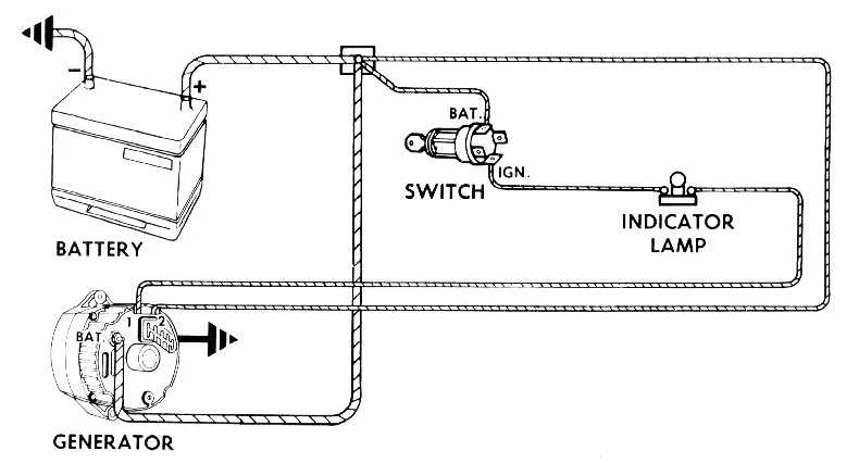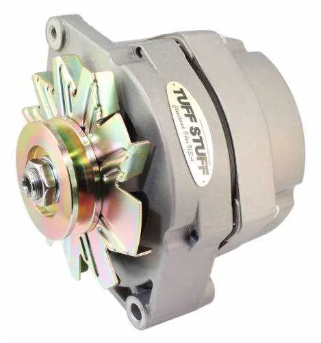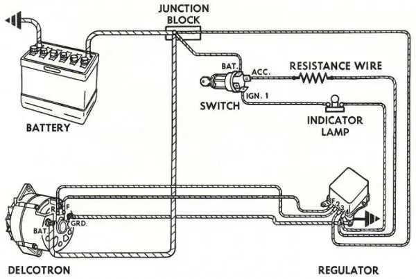
Ensure correct connections when setting up the charging system in your GM vehicle by following the wiring paths from the power source to the regulator and battery. For seamless operation, focus on the connection between the voltage regulator and the power input terminal. A clear and strong contact between these two components is vital for efficient energy transfer.
Start by verifying the ground connection to the battery. This is one of the most common issues that leads to charging failure. The negative terminal must be securely linked to the vehicle’s chassis to allow smooth current flow. Double-check the integrity of this ground before moving on to other steps.
Next, ensure proper attachment of the main power cable to the battery. It should be tightly secured at both ends to avoid any voltage loss. A loose connection here can prevent the vehicle from receiving the necessary power to charge properly. Check for any signs of wear or corrosion that could impede this connection.
Make sure to trace all connections from the regulator to the output terminal on the generator. It’s crucial that the wire is free of any obstructions and well-insulated to prevent short circuits. Pay close attention to the route of the wire to avoid accidental interference with other systems in the engine compartment.
Regularly inspect the vehicle’s electrical system to prevent potential failures. Look for signs of corrosion or fraying in the wiring, especially at connection points. Replacing any damaged components promptly ensures the charging system will function as designed, providing optimal performance and reliability.
GM Charging System Electrical Connections

For GM vehicles, proper setup of the electrical connections in the charging system is crucial for optimal performance. Here’s a step-by-step guide to ensure correct installation.
- Battery Cable (B+) Connection: Attach the positive battery cable to the large terminal on the rear of the component. Ensure it is tightly secured to avoid power loss.
- Voltage Regulator Input: The input wire for voltage regulation connects to the alternator. This controls the charging rate based on the system’s voltage needs.
- Ground Wire: Securely connect the ground wire to a solid, rust-free metal point on the engine block. A loose or corroded ground will cause poor performance.
- Exciter Wire: This wire is connected to the ignition switch. When the engine is running, it provides the necessary signal to start the charging process.
For modern GM models, check the exact pinout based on your vehicle year, as the system components may slightly vary. Always use manufacturer-specific components to ensure compatibility and reliability.
When testing the system, make sure to measure the voltage output directly at the battery terminals. The voltage should range between 13.5V to 14.5V when the engine is running at idle speed. Any significant deviation may indicate a fault within the electrical setup.
Understanding the GM Generator Pinout and Connector Configuration

For proper functioning, it’s crucial to know the specific pins on the GM generator connector. Ensure that the wiring is aligned with the correct terminal on the vehicle’s electrical system.
The “L” terminal (often labeled as “field” or “light”) is typically used to activate the regulator, signaling that the unit is running. If this connection is not made, the unit won’t function as expected.
The “S” terminal connects to the system’s battery and is responsible for maintaining the charge. It’s critical that this terminal is properly linked to ensure the battery receives the right voltage to stay charged.
The “F” terminal is commonly linked to the field coil. Proper connection here allows the unit to receive a fluctuating signal that adjusts the output voltage as needed by the engine’s demand.
Additionally, pay attention to the ground connection. Without a solid ground path, the device can fail to operate correctly, often resulting in erratic or zero output.
Finally, always check that the terminals are free from corrosion and ensure a tight, clean connection. Poor contact can lead to a complete failure of the unit or intermittent charging issues.
Step-by-Step Guide to Identifying Key Wires in GM Alternator System
Start by locating the main charge wire, typically the thickest cable attached to the positive terminal. This wire is responsible for carrying power from the generator to the battery. It usually connects directly to the battery or the fuse box.
Next, find the ground wire, which is essential for completing the electrical circuit. This cable often runs from the alternator housing to the vehicle’s chassis or engine block.
The signal wire, usually smaller than the main charge cable, is vital for the voltage regulator. This wire communicates the alternator’s status to the vehicle’s electrical system, ensuring proper voltage is maintained. It is commonly attached to the back of the unit.
Look for the “field” wire, often connected to the voltage regulator. This wire helps control the alternator’s output by adjusting the magnetic field inside the rotor. It is often a thin wire running from the regulator to the rotor section of the alternator.
Finally, locate the warning light or excitation wire. This wire is linked to the dashboard warning light, signaling when the generator isn’t functioning correctly. It’s typically a small gauge wire leading from the unit to the instrument cluster.
Troubleshooting Common Electrical Issues in GM Charging Systems
Check the connections at the battery terminal first. Corrosion or loose contacts can prevent proper charging. Ensure the positive and negative cables are tight and free from damage. If corrosion is present, clean the terminal with a mixture of baking soda and water.
If the engine is not charging despite everything being connected, inspect the voltage regulator. A faulty regulator may prevent the system from charging, even when the connections are secure. Use a multimeter to measure the voltage at the battery; it should be between 13.8 and 14.2 volts when the engine is running. If it’s lower or higher, the regulator could be malfunctioning.
Examine the connections to the stator windings and rotor. A poor connection here can cause intermittent charging, especially under load. Look for frayed wires or signs of melting insulation. If damaged, replace the affected components immediately.
Inspect the ground connection. A bad ground can lead to erratic voltage output. Make sure the grounding strap or cable is securely attached to a clean, unpainted metal surface on the engine block or frame.
Lastly, test the diode bridge. Faulty diodes can cause the system to fail to charge. A diode checker or multimeter with diode test mode can be used to confirm if any diodes are shorted or open. If a problem is detected, replace the defective component.