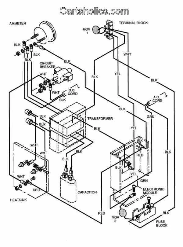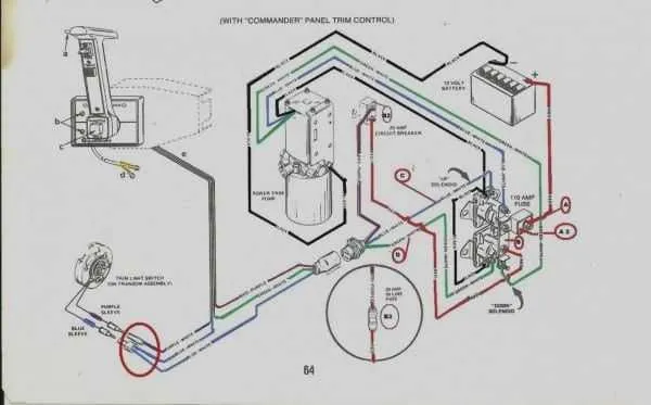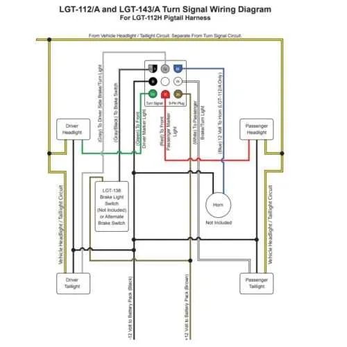
Ensure proper connections when handling a 36V electric system in your vehicle. This includes accurately linking the battery terminals, controller, and motor. Pay attention to polarity to avoid malfunction and damage to components.
Always use quality components that match the specifications of the system. Cheap or mismatched parts can cause voltage drops, overheating, or complete failure of the electric drivetrain.
Monitor amperage throughout your connections. The electric current should flow smoothly through the system without excess resistance. Use fuses and breakers as necessary to protect against overloads.
It’s essential to ensure the controller is programmed for your specific setup. Each system requires custom settings to optimize performance and safety.
Lastly, check that grounding is solid and properly placed to prevent interference or electrical shorts, especially in wet conditions.
36V Golf Cart Electrical Connections

Ensure proper alignment of all components before beginning any electrical work on your 36V vehicle. Start with the battery pack–connect the positive terminal to the motor’s corresponding input, and then the negative to the frame or designated grounding point. Always confirm that wires are securely attached to avoid power loss.
The controller should be directly linked to both the motor and the power supply, maintaining a balanced distribution of current. Double-check that the main switch is wired correctly to engage and disengage the entire system safely.
Check each connection regularly for signs of wear or corrosion, especially around the battery posts. This prevents voltage drops and potential system failure. If adding accessories, ensure they’re connected to the correct terminals and include a fuse to protect the circuit from overloads.
When working on the electrical layout, ensure that the cable gauge is sufficient for the current draw. An undersized wire can overheat, causing damage to components. Use color-coded insulation to clearly differentiate between each connection, simplifying troubleshooting.
Understanding the Power Source and Battery Layout
Start by ensuring proper alignment of the power cells. Each unit should be connected in series, ensuring the correct positive and negative terminals are linked. This configuration guarantees the system functions at optimal capacity.
Key recommendation: Always use cables with sufficient gauge to handle the total current demand. Overly thin wires can lead to excessive heat buildup and potential failure. A gauge of at least 6 AWG is recommended for most setups.
For maximum performance, link the positive terminal of one battery to the negative terminal of the next. This chain will provide the required energy output while maintaining balance across the units. Avoid any short-circuits by double-checking each connection.
Ensure the main power terminal of the system is securely fastened and properly insulated. A loose or poorly insulated terminal can cause energy loss and pose safety risks. Also, use appropriate connectors that are corrosion-resistant, especially in outdoor environments.
Finally, monitor the voltage levels across all individual units regularly. Imbalanced charge levels can drastically reduce overall efficiency and lifespan of the setup. Regular maintenance and periodic checks are vital.
Key Connections for Motor and Controller in 36-Cell System
Motor power connections should be made to the main terminals of the controller, typically marked as “M” for motor and “B+” for battery. Ensure that these connections are made with heavy-duty cables capable of handling high current loads. A poor connection can lead to overheating and performance issues.
Controller ground connection should be secured to the frame or a designated ground point to avoid electrical interference. This is critical for proper controller function and safety.
Throttle input from the accelerator should be properly wired to the controller, ensuring a smooth transition from idle to full speed. Throttle wires are typically color-coded, with common colors being black for ground and green for signal.
Solenoid activation must be connected to the controller’s signal terminal to engage the motor when the accelerator is pressed. A faulty solenoid or incorrect wiring can cause the motor to fail to start.
High current fuses should be placed between the battery and controller to protect against short circuits and overloads. Always use the manufacturer-recommended fuse rating to ensure the system remains safe.
Reverse switch wiring connects directly to the controller and allows for direction control of the motor. Ensure that this connection is clean and properly configured to avoid reversing errors or potential damage.
How to Troubleshoot Common Electrical Issues in 36V Golf Cart

Start by inspecting the battery connections. Corrosion or loose terminals can prevent proper power flow. Clean any corrosion with a wire brush and ensure all connections are tight.
- Check each terminal for buildup or dirt.
- Ensure battery cables are not frayed or damaged.
- Use dielectric grease to prevent future corrosion.
If the power is intermittent or the vehicle stops unexpectedly, test the motor connections. Faulty or loose contacts can result in power loss, so secure all bolts and connections. Make sure to verify the condition of the motor controller as well.
- Disconnect the power before inspecting the motor and controller.
- Look for burnt or damaged parts in the controller.
- Measure resistance with a multimeter to confirm motor performance.
Next, verify the fuses and circuit breakers. A blown fuse is often a simple explanation for a malfunction. Replace any blown fuses with the correct rating to restore operation.
- Check fuse box for damaged components.
- Replace blown fuses with identical ratings (ampere and size).
- Inspect the fuse box itself for cracks or wear.
Inspect the throttle system. A malfunction in the throttle pedal or potentiometer can prevent acceleration. Test the throttle sensor with a multimeter to ensure proper function.
- Test the throttle pedal wiring for continuity.
- Ensure the potentiometer operates smoothly and doesn’t stick.
- Adjust or replace faulty throttle components.
If the vehicle still fails to start or move, check the charger. An issue with the charging system could result in insufficient battery power. Confirm that the charger is functioning correctly and that the charging port is not obstructed.
- Inspect the charging cable for wear or breakage.
- Ensure the charging port is clean and free of debris.
- Test the output voltage from the charger to ensure it matches the battery requirements.
Regular maintenance and periodic checks on these key components will help avoid common electrical failures in your 36V electric vehicle.