Start by locating the throttle trigger mechanism near the right handle–inspect the return spring placement and ensure the linkage connects precisely with the carburetor lever. Misalignment in this section often causes acceleration delays or inconsistent idle performance.
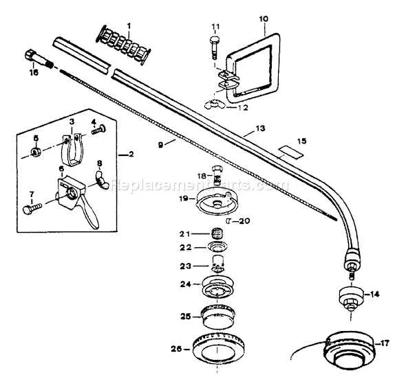
The shaft assembly includes an inner drive cable encased in a metal tube. Regularly check both ends for fraying or wear, especially at the connection points to the engine clutch drum and cutting head gear mechanism. Replace immediately if any stiffness or unusual noise is observed during rotation.
Air intake modules consist of a foam or felt filter, a plastic cover, and mounting brackets. Ensure the filter material is clean and seated flush to prevent dust ingress. A distorted or degraded seal around this area frequently results in power loss during operation.
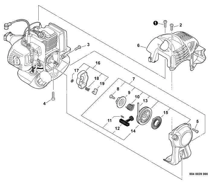
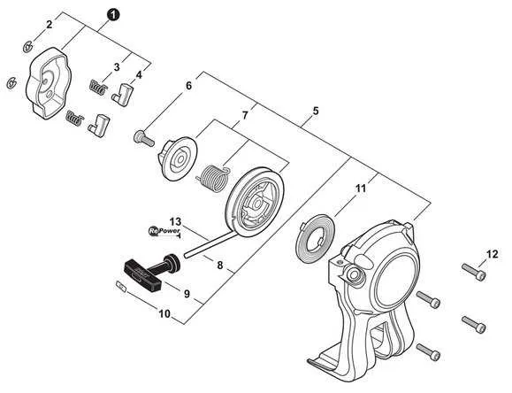
Within the engine housing, the flywheel, ignition coil, and recoil starter interact closely. If starting becomes difficult, inspect the pawls and starter spring tension. Additionally, verify the coil air gap is within manufacturer tolerance–typically around 0.012 inches.
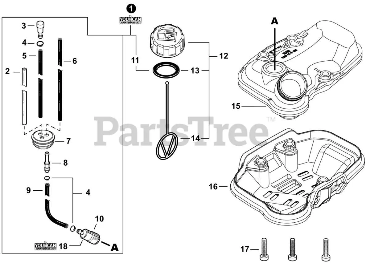
Fuel system components include a primer bulb, flexible lines, and a diaphragm-style carburetor. Check for hardening of hoses or leaks around grommets. Replacing all rubber elements annually is recommended to prevent vacuum issues and ensure consistent fuel delivery.
Detailed Assembly Breakdown
Begin by identifying the driveshaft housing and check for any visible cracks or wear on the flex cable. Replace immediately if frayed or rusted to prevent operational failure.
Inspect the clutch drum and liner for excessive scoring or discoloration–these indicate overheating and should be swapped to maintain torque efficiency. Ensure the return spring sits firmly within the clutch shoe assembly.
Focus next on the gearbox unit. Confirm gear teeth are evenly meshed without chipping. Lubricate the pinion and worm gear thoroughly using lithium-based grease to minimize friction damage during high-load use.
Examine the powerhead isolators; any rubber mounts showing signs of hardening or cracks must be exchanged to reduce vibration transfer to the handle system. Reinforce throttle linkage alignment to ensure responsive control input.
Verify that each fastener securing the coupler and shaft extension is torqued to specification. Use thread-locking compound where indicated by service manual torque charts to prevent loosening under vibration.
Locating and Identifying PAS 225 Shaft Assembly Components

Start by removing the attachment head using a hex wrench to expose the internal coupling mechanism. Ensure the tool is disconnected from any power source before proceeding.
- Upper Tube Housing: Slide off the outer casing to access the inner steel drive rod. Inspect for wear or scoring near the spline end.
- Drive Shaft: This flexible or solid rod transmits torque. Check the spline teeth at both ends for signs of rounding or deformation.
- Clamp Collar: Located midway on the shaft housing. Loosen it to separate the upper and lower sections of the unit. Look for a plastic spacer or rubber sleeve to ensure proper alignment.
- Gearbox Coupling: Found at the end of the lower extension. Examine the female socket and alignment pin for debris or misalignment.
- Throttle Cable Routing: Follow the cable along the shaft to check for pinches or disconnections. Verify that the trigger spring is functioning smoothly.
When reassembling, apply lithium-based grease to both ends of the drive rod. Tighten all fasteners to factory torque values to avoid vibration during operation. Replace any damaged splines or bushings immediately to maintain performance.
Understanding the Role of the Powerhead in the PAS 225 System

Replace worn seals and gaskets in the main engine housing immediately to prevent compression loss. Ignoring minor air leaks can reduce fuel efficiency and damage internal components.
Ensure the throttle cable is correctly tensioned. Sloppy or over-tight connections lead to delayed response or poor acceleration during operation.
Use only manufacturer-recommended two-stroke oil mixed at a 50:1 ratio. Incorrect mixtures cause carbon buildup on the piston crown and exhaust port, reducing output.
Clean the spark arrestor screen after every 10 hours of use. A clogged screen limits exhaust flow, straining the crankcase and reducing torque.
Inspect the recoil starter spring and pawls for fatigue. If the engine fails to engage quickly, excessive cord pulls may crack the flywheel key or shear the crankshaft pin.
Keep the cooling fins and air intake grill clear of debris. Overheating the cylinder can warp the head gasket and damage the connecting rod bearings.
Monitor for abnormal vibrations near the clutch housing. This may indicate worn drum bushings or misalignment with the drive shaft coupler.
How to Match Replacement Attachments with Correct Diagram Sections

Always identify the exact shaft type and coupling mechanism before selecting a substitute implement. Inline drive connectors differ from splined or square-end shafts, which directly affects compatibility with specific tool heads.
Refer to section labels showing engine output assemblies and coupler housings. These segments typically include keyed alignment visuals and fastener placement–essential for confirming fitment with blades, trimmers, or edgers.
Cross-check the serial range printed near the throttle housing with the technical sheet index. Components often vary across production years, even within similar models. Serial mismatches cause incorrect mounting interfaces, especially with gear-driven extensions.
Locate the exploded view highlighting the attachment receiver. This area contains internal collar sleeves and spring-loaded latches. Match tab notches and locking pin configurations precisely to avoid detachment during use.
Avoid relying on visual similarity alone. Use reference codes typically found near the tool mount hub, and trace them to the index list that corresponds to specific assembly breakdowns. This ensures exact alignment with drive shaft geometry and operational torque rating.