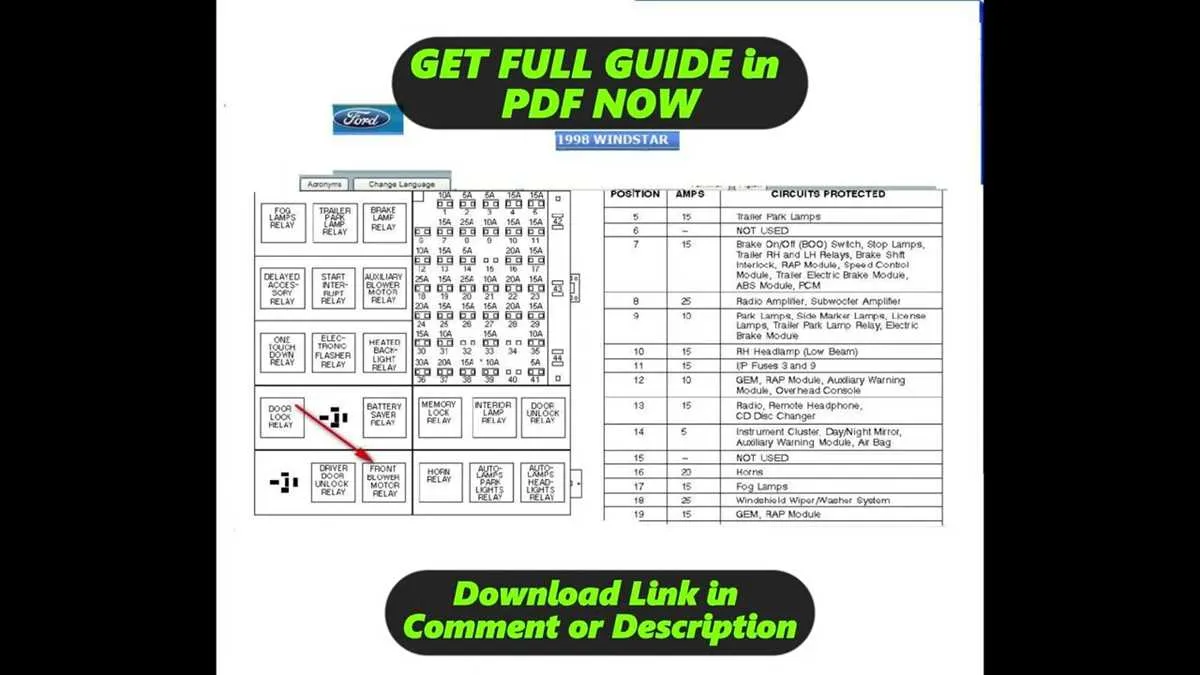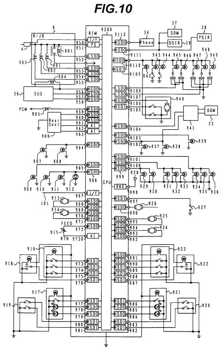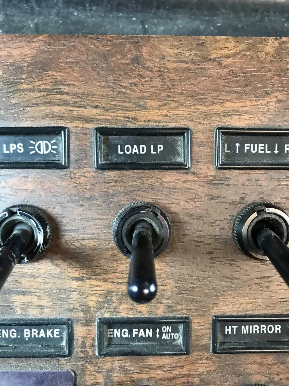
Start by locating the primary electrical distribution block situated beneath the left side of the dashboard, directly behind the kick panel. Remove the cover carefully to reveal a set of clearly labeled connectors and protection elements. Each slot corresponds to a specific circuit, including lighting, climate control, engine management, and auxiliary systems.
Identify the power distribution points using the numeric and color-coded key typically printed on the inner side of the protective lid. For example, slot 5 usually links to headlamp functionality, while slot 12 often powers the HVAC blower motor. Use a test light or multimeter to confirm voltage presence before replacing any component.
Be aware of common failure points such as corroded terminals or overloaded circuits, particularly near the accessory plug outputs. If troubleshooting lighting or engine startup issues, pay special attention to the rows near the lower section of the grid, as they frequently manage ignition and safety-related systems.
For modifications or the addition of new equipment, use the auxiliary slots typically positioned in the upper right corner of the array. Ensure to match the amperage rating and wire gauge for any add-ons to prevent overload. Always disconnect the battery before servicing any element within this compartment to avoid accidental shorts.
Electrical Layout and Component Placement
Start by checking the main relay block located beneath the dashboard on the driver’s side. Identify each circuit by referencing the labels stamped beside each terminal–common ones include IGN SW BATT, HTR A/C, ECM, and ABS.
The power distribution hub includes blade-style sockets organized in vertical rows. For example, the top-left slot often governs the headlamp low beam, while adjacent slots may connect to HVAC and clutch interlock systems.
Use a test light or multimeter to verify voltage across terminals. If you encounter a dead accessory, inspect the associated mini-cartridge or micro-style safety link. A burnt trace or discolored plastic usually indicates failure.
Pay close attention to spares marked as “IGN A SPARE” or “ACC SPARE”–these can be reassigned if a critical circuit is blown. Ensure replacements match the ampere rating indicated by the embossed symbol near the receptacle.
For lighting and trailer functions, review the auxiliary distribution bay located behind the kick panel. Use OEM schematics to trace connections, especially for non-functioning marker lights or turn signals tied to the chassis harness.
Fuse Panel Location and Access Points in 2005 Peterbilt 379

Begin by opening the driver’s side door and removing the lower dash cover beneath the steering column. This section conceals the primary electrical junction box, typically mounted behind the kick panel. Use a 7mm socket or Phillips screwdriver to detach the fasteners.
For secondary access, check the right side of the dashboard behind the glove compartment. Some configurations include auxiliary relays and breakers here, especially for aftermarket or sleeper cab systems. To access this area, release the glove box stops and tilt it downward.
In sleeper-equipped models, additional circuitry may be mounted under the bunk. Lift the mattress platform and inspect the forward-facing bulkhead or compartment walls for enclosed modules. Always disconnect the battery before handling any internal components to prevent short circuits.
Identifying Functions of Each Fuse and Relay in the Diagram

Start by locating the legend label typically printed near the cover or on a separate reference card. Match the slot numbers with the components they control.
- Slot 1: Controls marker lamps. A failure here results in no clearance lights.
- Slot 3: Assigned to the ABS system. Inspect if ABS warning is illuminated.
- Slot 6: Linked to HVAC blower motor. Blower malfunction often traces back to this point.
- Slot 9: Reserved for engine ECM power. Engine won’t crank if this link is broken.
- Slot 12: Manages trailer turn signals. Check during trailer light issues.
- Slot 14: Supplies power to cab dome illumination.
- Slot 16: Dedicated to the instrument cluster. No gauge response often originates here.
Relays are equally critical. Each serves a switching function for high-amperage circuits:
- Relay A: Activates main ignition circuit. Symptoms of failure include no key-on power.
- Relay B: Operates fuel pump delivery. Hard start may indicate issues here.
- Relay D: Engages the headlight system. If low beams don’t function, test this relay.
- Relay F: Handles wiper motor engagement. Replace if wipers are inoperative.
Always verify with a multimeter and consult the manufacturer’s layout for model-specific configurations. Avoid assumptions based solely on numbering–variations exist across production batches.
Common Electrical Issues Linked to Specific Fuses in the 2005 Model
Loss of dashboard lighting often traces back to the 5A circuit responsible for the instrument cluster backlight. Inspect the slot labeled “ICL” and verify the integrity of the mini-blade connector; minor corrosion can lead to intermittent failures.
Non-functioning HVAC controls are typically caused by a faulty 10A unit tied to the climate control module. Look for the terminal marked “CLMT CTRL” and check for loose contact points, especially after vibration-heavy driving conditions.
Starter motor relay not engaging? The issue commonly stems from the 20A relay feed supporting the ignition switch. This is usually connected through the position marked “IGN SW PWR.” Replace the component only after testing continuity with a multimeter.
Marker lights not operating may be linked to a blown 15A safety circuit serving the exterior lamp array. The associated socket, often labeled “MRKR LMP,” should be tested under load as hairline cracks in the terminal base can cause false positives during simple voltage checks.
Radio and auxiliary ports dead? Target the 10A branch labeled “AUX PWR.” Ensure no aftermarket splice or bypass has overloaded the line–this is a frequent source of electrical backfeed damaging adjacent connections.