To ensure reliable operation of your temperature regulation setup, connect the coil terminals to a consistent 24-volt AC source. This voltage activates the electromagnetic switch, allowing safe and efficient control of high-current circuits without direct manual intervention.
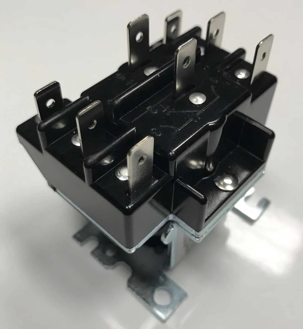
Proper terminal identification is critical: typically, two pins serve as coil connections, while the others correspond to the common, normally open, and normally closed contacts. Confirming these points prevents accidental short circuits and system failures.
Using appropriately rated contacts for load switching ensures longevity and reduces heat buildup. Always verify compatibility between the actuator and the control circuit to maintain optimal performance and safety.
24V Control Switch Connection Guide
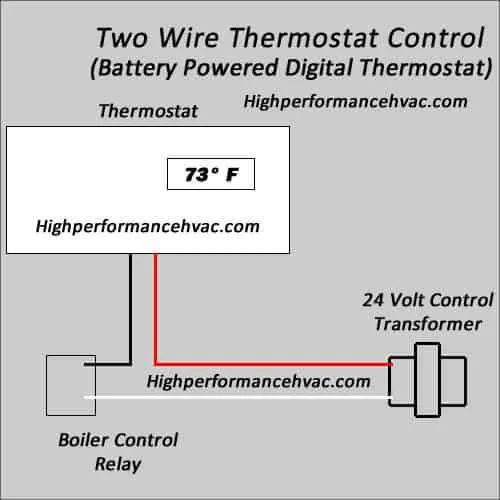
Connect the low-voltage coil terminals to the thermostat output and common line to ensure proper activation. The coil typically requires a nominal 24 volts AC for operation. Verify polarity where applicable, although most coils are AC and polarity insensitive.
For the power circuit, link the incoming power source line to the common contact of the switching device. The load line should connect to the normally open terminal, allowing current flow only when energized. Use appropriate gauge wiring rated for the load current to avoid voltage drops or overheating.
Include a fuse or circuit breaker on the supply side for safety. Confirm that all connections are secure and insulated. Ground the metal enclosure to prevent electrical hazards.
| Terminal | Function | Connection Point |
|---|---|---|
| Coil + | Activation Input | Thermostat output (24VAC) |
| Coil – | Common Line | Neutral or transformer return |
| Common Contact | Power Input | Line voltage source |
| Normally Open Contact | Power Output | Connected load (fan, compressor, etc.) |
Identifying and Connecting Relay Coil Terminals in 24V HVAC Systems
Locate the coil terminals by checking for the smallest pair of contacts on the electromagnetic switch. These are usually labeled A1 and A2 or marked with a coil symbol. Verify coil voltage rating to ensure compatibility with the control circuit’s power source.
Use a multimeter set to measure resistance across the coil terminals; typical values range between 50 to 200 ohms. An open circuit indicates a damaged coil, while a shorted coil will show near-zero resistance, both requiring replacement.
Connect the control voltage lines directly to the coil terminals, respecting polarity if specified. The positive side usually connects to A1, and the negative to A2, but consult the manufacturer’s specifications to confirm.
Ensure secure and insulated connections to avoid accidental shorts or signal interference. Employ crimp terminals or solder joints with heat-shrink tubing for reliable contact and mechanical stability.
After installation, test activation by energizing the coil circuit and listening for the characteristic clicking sound indicating proper engagement of the internal switch.
Wiring the Relay Contacts for Fan and Compressor Control

Connect the switching terminals to ensure proper activation of both the blower and compressor units. Use the normally open (NO) contact for powering the fan motor and the common (COM) terminal as the source connection.
- Identify the contact set labeled NO and COM on the switching device.
- Run the line voltage from the power supply to the COM terminal.
- Connect the NO terminal to the fan motor’s live input lead.
- For the compressor, use a separate switching device or the second set of contacts on a dual-switch model, following the same COM to source and NO to compressor line connection.
Ensure the control coil is energized by the thermostat output to close the contacts and allow current flow to the load components.
- Verify that the coil voltage matches the control signal specifications.
- Use proper gauge conductors rated for motor start currents to avoid voltage drop.
- Install a protective fuse or circuit breaker on the supply side to prevent overload damage.
- Confirm all connections are secure and insulated to prevent short circuits or accidental disconnections.
Double-check polarity and grounding to maintain system safety and reliable operation of both the fan and compressor units.
Testing and Troubleshooting 24V HVAC Relay Wiring for Proper Operation

Begin by verifying the control voltage at the coil terminals using a multimeter set to AC voltage mode. It should read approximately 24 volts when the system calls for activation. If no voltage is detected, inspect the transformer and thermostat connections for faults.
Check coil continuity with an ohmmeter; a healthy coil typically measures between 50 to 120 ohms. An open circuit indicates a burned-out coil that requires replacement. Excessive resistance can suggest coil damage or corrosion.
Ensure that the contact terminals are clean and free of oxidation or pitting, which can prevent proper current flow. Use a contact cleaner or gently file contacts if necessary.
Test the switching function by applying control voltage and confirming that the contacts close, completing the load circuit. You can measure continuity across the output terminals when energized. Lack of continuity signals mechanical failure or stuck contacts.
Inspect all connection points for tightness and corrosion, especially at terminal blocks and splices. Loose connections cause intermittent operation and voltage drops.
Use a clamp meter to monitor current draw on the load side. Values significantly above the device’s rating may indicate short circuits or overloaded components downstream.
If coil voltage and load current are correct but the device does not actuate, replace the unit, as internal mechanical failure is likely.