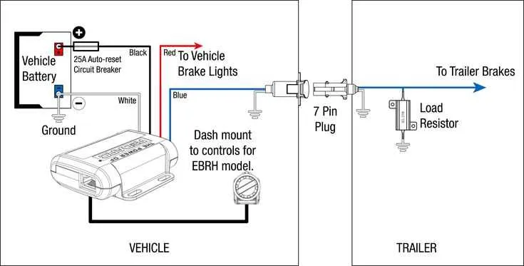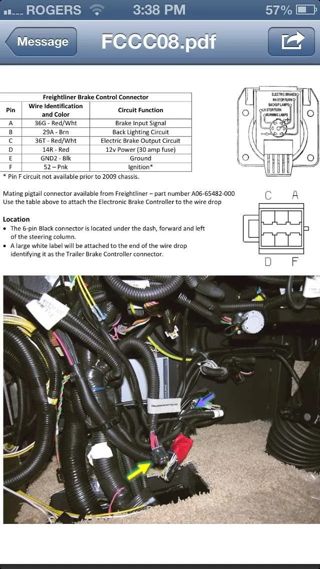
For reliable performance, connect the electrical control system of your hauling setup following the exact pin configuration recommended by manufacturers. Use a multi-core cable that supports at least 12 AWG gauge to ensure sufficient current flow for the activation coil.
Always confirm that the ground wire is securely attached to a clean, unpainted metal surface on both the towing and towed units. This minimizes the risk of intermittent operation caused by poor conductivity or corrosion.
Integrate a dedicated power feed fused at 15 amps to protect the circuit from overloads and potential shorts. For signal input, match the output of the controller box with the actuator coil terminals precisely, avoiding any cross-wiring that may lead to malfunction or premature wear.
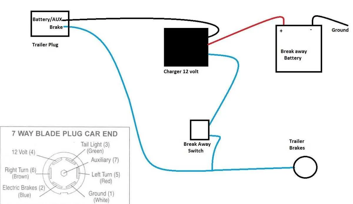
Proper color coding of cables–typically white for ground, blue for activation signal, and red for power–simplifies troubleshooting and maintenance, reducing downtime and enhancing safety on the road.
Connector Setup for Powered Tow Vehicle Stopping System

Use a four-pin or seven-pin plug depending on the stopping mechanism’s complexity. The signal wire typically runs from the towing unit’s brake controller output to the electromagnetic actuators on each wheel. Grounding must be secure; connect the chassis ground wire directly to the frame to avoid electrical interference.
For proper current flow, ensure the power supply wire is rated for at least 14 gauge to handle the actuator load. Attach the white wire to the common ground, the blue wire to the control output, and the black or red wire to the battery positive if your system includes a manual override or charging line.
Confirm all connectors are corrosion-resistant and sealed to prevent moisture ingress. Use dielectric grease on terminals to enhance conductivity and reduce oxidation. When routing cables, avoid sharp bends and secure them with clips to prevent abrasion or disconnection during movement.
Test continuity before finalizing connections by activating the brake controller and measuring voltage at the actuator terminals. A consistent voltage drop across each wheel’s electromagnet confirms correct setup. Replace any faulty connectors or damaged cables immediately to maintain safety and reliability.
How to Identify and Connect Brake System Wire Colors

Start by locating the color-coded conductors commonly used in standard setups: blue for the brake controller output, white as the ground, and green for the right signal circuit. Brown typically serves the tail or running lights, while yellow is assigned to the left signal line.
Verify the ground wire by testing continuity between the white conductor and the vehicle chassis. A poor ground can cause malfunction, so ensure a clean, rust-free connection point.
Connect the blue lead from the towing unit’s control box directly to the brake actuator input on the towed unit. Use ring terminals and secure connections to avoid signal loss under vibration.
Match signal conductors (green and yellow) to their respective side lamps, confirming turn signal function with a multimeter set to continuity or voltage detection.
Before finalizing, apply dielectric grease on all connectors to prevent corrosion and check for proper operation using a manual override on the control module or a test light.
Step-by-Step Guide to Connecting the Brake Controller to the Tow Rig
Begin by selecting a controller with an adjustable output for better control. Mount the device inside the cab in a location that allows easy access. Ensure that it is positioned securely to prevent movement during travel.
Next, locate the power supply, typically the 12V source from the vehicle’s electrical system. Connect the positive terminal to the power input on the controller, using a fuse-rated for the correct amperage to prevent damage in case of a short circuit. For grounding, find a suitable metal surface on the vehicle’s frame to ensure a solid connection for optimal performance.
For signal connection, run a wire from the controller to the activation circuit in the rear. This will allow the controller to send a signal when the pedal is pressed. Ensure the wire is long enough to avoid stretching and is protected with heat shrink or electrical tape to prevent exposure to the elements.
Next, connect the controller to the braking system at the rear by linking the two through the designated terminal. This circuit ensures that the trailer’s braking mechanism engages in sync with the vehicle’s braking actions. Use a sturdy connector for this part, ensuring a tight, corrosion-resistant fit.
Double-check all connections for tightness and security before proceeding. After making sure there are no exposed wires, test the setup by applying the brake to see if the system engages smoothly. Adjust the controller’s sensitivity as needed to match the performance preferences.
Finally, ensure that all connections are properly insulated and protected from moisture. Use waterproof connectors where necessary to safeguard against damage from road conditions and weather.
Troubleshooting Common Wiring Issues in Electric Trailer Brakes
Ensure proper power delivery by checking the connections at the power source and the control unit. A loose or corroded connection can cause inconsistent performance or complete failure.
- Test the Fuse: A blown fuse is a common culprit. Replace any faulty fuses to restore the circuit.
- Inspect Grounding Points: A poor ground connection will result in weak or no operation. Clean the contact points and ensure a solid connection.
- Check for Frayed or Damaged Cables: Worn-out insulation or visible damage to the cable can lead to intermittent issues. Replace or repair any damaged sections promptly.
Verify the integrity of the controller and adjust the sensitivity if needed. An incorrect setting can lead to insufficient response or too harsh activation.
- Ensure Proper Voltage Supply: Test the system to ensure it receives the correct voltage. Insufficient voltage may cause weak activation.
- Test the Brake Magnets: Faulty magnets may result in poor stopping power. Check for physical damage or wear and replace if necessary.
Test each component one by one to isolate the issue, and perform a thorough inspection of all connections. Often, troubleshooting a problem comes down to simple connection issues or a damaged part in the system.