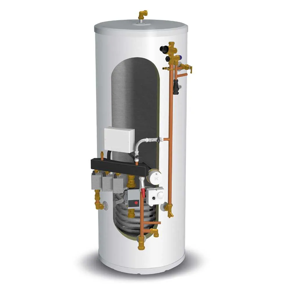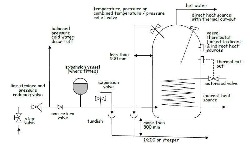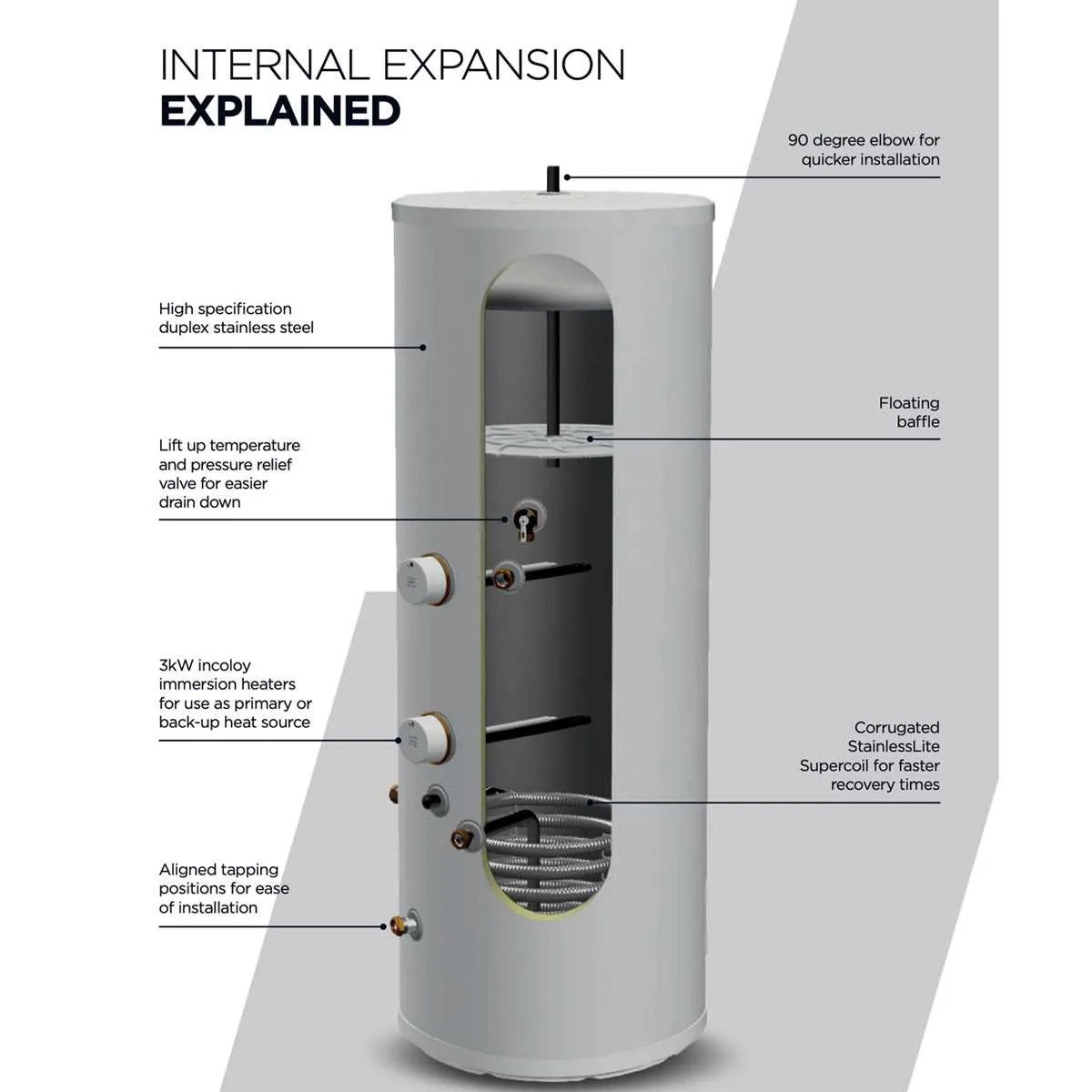
Ensure all components are rated for the operating pressure to maintain safety and avoid leaks. This type of sealed thermal storage requires a reliable expansion vessel and a pressure relief valve positioned according to manufacturer guidelines.
Correctly position the cold feed and outlet connections to guarantee efficient circulation and prevent airlocks. Incorporate a temperature and pressure monitoring device close to the heat source to track system performance accurately.
Use copper or stainless steel piping designed for pressurized environments. The layout should allow straightforward access to isolation valves and servicing points, minimizing downtime during maintenance.
Step-by-step connection of safety and control valves in sealed storage vessel setup
Begin by mounting the pressure relief valve directly on the designated outlet of the sealed vessel, ensuring it faces outward and is accessible for maintenance. Use PTFE tape on threaded joints to guarantee a watertight seal. Attach the expansion relief valve downstream, connecting it to the expansion pipe that leads outside or to a safe discharge point.
Fit the temperature and pressure relief valve next, positioned on the side or top of the storage unit as specified by manufacturer guidelines. Connect the discharge pipe firmly, directing it vertically downwards to prevent backflow and avoid blockages.
Install the automatic air vent valve at the highest accessible point of the system to allow trapped air to escape continuously. Connect the zone valve and thermostat sensor wiring according to the control panel instructions, ensuring cables are secured and insulated from moisture.
Complete the setup by verifying all valves operate freely: manually test the pressure relief valve by lifting its test lever to confirm flow, then check that all discharge pipes lead to visible safe areas without restrictions or kinks.
Finally, perform a pressure test on the entire assembly at manufacturer-recommended settings to detect leaks or malfunctioning valves before commissioning the closed-loop supply unit.
Key Pipework Layout to Integrate an Unvented Storage Unit with Existing Plumbing

Connect the cold feed directly from the mains supply using a double check valve to prevent backflow. This ensures a continuous and safe feed without relying on gravity tanks.
Incorporate a pressure relief valve and an expansion relief valve on the storage vessel outlet to release excess pressure and avoid damage due to thermal expansion. Both valves should discharge into a visible and safe discharge pipe terminating near a drain.
Fit a pressure reducing valve before the inlet if mains pressure exceeds manufacturer limits, typically above 5 bar, to protect internal components.
Use a non-return valve on the outlet line to prevent reverse flow and contamination of the potable supply.
Connect the distribution feed to the existing pipework with isolation valves on both supply and return lines for ease of maintenance and emergency shutoff.
Ensure all copper or suitable piping has proper support and avoids sharp bends to maintain flow efficiency and reduce stress on joints.
Install a thermal cut-out or thermostat control in line with the manufacturer’s guidelines to regulate temperature and prevent overheating.
Integrate a safety expansion vessel sized according to the total volume of stored liquid and system pressure to accommodate volume changes during heating cycles.
Testing Procedures and Troubleshooting Common Setup Issues

Begin by verifying the pressure relief valve operation: manually lift the test lever and confirm immediate water discharge without leakage when released. Replace the valve if it fails to open or leaks continuously.
Check the expansion vessel pre-charge pressure with a gauge; it should match manufacturer specifications, typically around 3 bar. Adjust or replace the vessel if readings fall outside the acceptable range.
Measure the system’s operating pressure when cold and during peak demand; typical cold fill pressure is 1.5–2.0 bar, rising to a maximum of 3 bar when heated. Pressure outside these limits indicates a filling or expansion issue.
Inspect all pipework connections for tightness and signs of leaks, focusing on joints near the heat source and safety devices. Tighten fittings or reseal with appropriate materials where leaks appear.
Test the thermostat and temperature sensors using a multimeter or temperature probe to ensure correct readings and responsiveness. Replace faulty sensors to avoid overheating or insufficient warming.
Ensure the non-return valve allows flow in the correct direction and does not restrict system pressure. Replace if any reverse flow or blockage is detected during inspection.
Confirm that the electrical supply to the heating element is secure, and all control units operate within their voltage and current ratings. Replace blown fuses or reset breakers as necessary.
Monitor the discharge pipe from the safety valve to ensure it is properly routed and unobstructed, preventing backpressure or accidental blockages that can cause pressure buildup.
Run a full cycle test by heating the storage vessel to operational temperature, then observe pressure fluctuations, valve activations, and temperature control accuracy. Address any irregularities immediately.