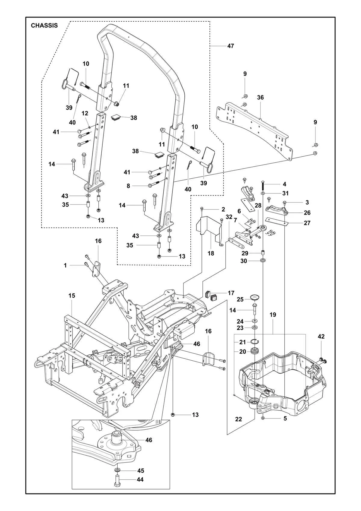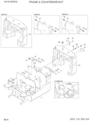
For those working on or maintaining the steering assembly of the Z425 mower, it is essential to have a clear understanding of its parts and their configuration. The efficient functioning of the control system depends on precise alignment and wear resistance, which can be assessed through an accurate schematic. Proper identification of each part will enable smoother repair or replacement processes.
Start by examining the central hub and its connection to the control rods, as these are the critical elements responsible for responsive maneuvering. Over time, wear can cause these parts to lose efficiency, affecting overall handling and steering accuracy. Regular inspection of the linkage system is highly recommended to prevent sudden malfunctions.
Next, focus on the tie rods and their interaction with the central pivot. If they are not aligned properly or have worn bushings, the mower may exhibit poor directional control. Ensure that each component is securely fastened and free of corrosion or debris that could impede smooth movement.
Lastly, don’t overlook the pitman arm and its corresponding connections to the wheel assembly. This part plays a pivotal role in converting rotational motion into the desired directional change. Proper lubrication and timely replacement of worn-out parts can prevent costly repairs in the long run.
Guidance Mechanism Layout

To resolve issues with the maneuvering system, start by reviewing the connection between the control arm and the wheel axles. The essential part for responsiveness includes the pivot rods that link the gear assembly to the front wheels. Inspect these for any wear or misalignment, which can lead to uneven handling.
The adjustable tie rods are key for proper alignment. If they are loose, the wheels will not track straight. Tighten or replace any faulty rods to ensure the machine turns accurately when the handle is engaged.
Examine the central linkages that interact with the frame for corrosion. These connections are pivotal in maintaining the precision of the direction of travel. Should any parts appear corroded or worn out, replace them promptly to avoid future failure.
Finally, check the hydraulic control system for leaks. Even a small loss of fluid can result in less responsive control. Ensure all hoses are intact and sealed, as leaks may not only diminish control but also damage the rest of the maneuvering setup.
Identifying Key Steering Parts in the John Deere Z425
To ensure proper function and smooth operation, it’s essential to recognize the major parts involved in the control mechanism. Below are the key parts and their roles:
- Axle Spindles: These connect the wheels to the vehicle’s frame. They are crucial for the mobility of the front wheels and maintaining the desired direction.
- Control Linkage: A set of rods and joints that translate operator input to the steering mechanism, ensuring responsiveness when changing direction.
- Hydraulic Cylinders: These are the heart of the system, providing the necessary force to adjust the wheel angle with minimal effort from the operator.
- Pivot Arms: They serve as the fulcrum for wheel movement. These parts allow the front axle to rotate, which changes the direction of the vehicle.
- Ball Joints: Located at various pivot points, they enable smooth movement and help absorb shocks from uneven terrain.
Regular inspection of these elements is critical to maintaining precision and avoiding costly repairs. If any part shows wear or malfunction, replacing it promptly can prevent more extensive damage to the entire system.
How to Troubleshoot Steering Issues in the John Deere Z425
Start by checking the hydraulic fluid level in the system. Low fluid can cause resistance or a lack of response in the control mechanism. If it’s low, top it up with the recommended fluid and inspect for leaks.
Next, inspect the belt for wear or damage. A slipping or broken belt can prevent proper turning. If any damage is found, replace it immediately to restore full functionality.
Ensure that the linkages and joints are not worn or loose. Loose or corroded connections can lead to imprecise movement. Tighten or replace any faulty parts to maintain smooth operation.
If the turning radius is uneven, check for air trapped in the hydraulic system. Bleed the system to remove any air pockets that may be causing inconsistent control.
Finally, examine the tires for proper inflation. Uneven tire pressure can affect the maneuverability of the machine. Adjust the air pressure to match manufacturer specifications.
Step-by-Step Guide to Replacing Steering Parts on the Z425
Start by disconnecting the battery to avoid electrical hazards. Use a wrench to remove the negative terminal. This step ensures safety throughout the repair process.
Next, lift the front of the mower using a jack or lift to gain access to the undercarriage. Secure it with blocks to prevent any movement during the procedure.
Remove the front wheels by loosening the bolts with a socket wrench. Set them aside for later reassembly.
Detach the assembly that connects the wheel hubs to the frame. This often involves removing several screws and bolts. Keep track of each part and its orientation for reinstallation.
Inspect the pivot points for wear or damage. If any part is cracked, bent, or overly worn, it must be replaced before proceeding.
Remove the worn bushings and bearings. If the components show signs of excessive friction, replace them immediately with new ones to ensure smooth operation.
Next, install the new pivot components by aligning them with the correct mounting holes. Ensure all parts fit securely, and use a torque wrench to tighten the bolts to the manufacturer’s specified settings.
Reassemble the wheel hubs by reversing the disassembly process. Make sure that each bolt is tight and that the alignment is precise to avoid any instability when in use.
Lower the front end back to the ground and check the tightness of all fasteners again. Ensure everything is secure before testing.
Finally, reconnect the battery. Power on the mower and test the movement of the front wheels. The steering mechanism should now operate smoothly without any unusual noise or resistance. If any issues remain, recheck all connections for tightness and alignment.