When diagnosing issues with the accelerator system in modern vehicles, it’s essential to understand the critical part responsible for monitoring pedal input and translating it into engine management signals. This component, typically found in fuel injection systems, plays a crucial role in ensuring proper engine response and smooth driving performance. Without it, the vehicle’s engine may fail to accelerate correctly or respond to throttle input appropriately.
Examine the internal structure and working principles of this part. It uses a variable resistor or potentiometer to measure the degree of pedal movement. These measurements are sent to the engine control unit (ECU), which adjusts the engine’s fuel delivery and air intake based on the data received. A malfunction in this system can lead to delayed acceleration, poor fuel efficiency, or even stalling at high speeds.
Familiarize yourself with the most common failure modes, such as electrical faults, wear and tear from prolonged use, or dirt buildup affecting the internal components. Understanding how to read the wiring and pinout connections, as well as interpreting the signal flow, can save considerable time during troubleshooting. Regular inspections and maintenance can prevent issues from escalating, ensuring long-term reliability and optimal engine performance.
Key Points to Check: Focus on continuity tests, voltage readings, and smooth motion of the input mechanism. The correct reading between input and output values ensures the system operates as intended.
Tip: If experiencing hesitation during acceleration or an irregular idle, inspect the wiring and connectors for any signs of corrosion or damage that could lead to inaccurate readings.
Understanding the Function and Wiring of the Intake Valve Control Mechanism
The component responsible for monitoring the angle of the accelerator plate is a critical part of the engine control system. To ensure proper engine response, this device sends real-time data to the ECU regarding throttle opening. Accurate readings enable precise fuel delivery and timing adjustments, optimizing overall engine performance.
Check the wiring connection to avoid any faults that could lead to irregular engine behavior. A common issue is loose or corroded wires, which can interfere with data transmission. Ensure that all connections are clean and tightly secured, preventing intermittent signals.
For diagnostics, use a multimeter to measure the resistance variation as the valve opens and closes. The voltage signal should increase smoothly as the throttle plate opens, without any sudden drops or spikes. Any abnormal fluctuations may indicate a malfunction in the system.
Visually inspect the mechanism for any physical wear or buildup of dirt, as these can hinder its operation. Regular maintenance and cleaning will keep the mechanism functioning properly and prevent long-term damage to the engine control unit.
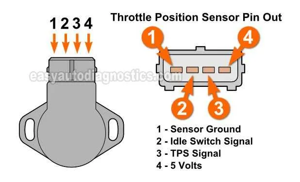
Understanding the Wiring Connections in a Throttle Position Sensor
The first step in troubleshooting a faulty input module is verifying the wiring connections. Always start by checking the power supply and ground connections to ensure proper voltage flow. A common issue arises when the signal wire loses continuity or is shorted to ground.
Red wire typically represents the power supply, often tied to the vehicle’s main electrical circuit. Confirm that the voltage matches the manufacturer’s specification, typically around 5V or 12V depending on the system. Any deviation could indicate an issue with the vehicle’s power distribution.
Black wire generally serves as the ground connection. A weak or loose ground can cause intermittent sensor readings, leading to inconsistent performance. Always inspect the connection for rust, corrosion, or wear, and ensure it is tightly secured.
The signal wire, typically color-coded as green or yellow, carries the data from the input module to the engine control unit (ECU). This wire should be free from damage or interference. A multimeter can be used to test the signal voltage under various throttle conditions to confirm accuracy.
If any of the wiring connections appear damaged, replace or repair them immediately. Consider using wire connectors and ensuring proper insulation to prevent accidental shorts. In addition, verify the connector terminals for wear, as poor contact can lead to data transmission failures.
Regular inspection of the wiring is crucial for maintaining optimal vehicle performance. Always refer to the manufacturer’s wiring chart for any system-specific peculiarities.
How to Identify Common Faults in Throttle Position Sensor Wiring

Start by inspecting the wiring harness for visible signs of wear, cuts, or fraying. Pay attention to areas where wires pass through tight spaces or near sharp edges, as these can cause short circuits or open connections. Broken or corroded connectors are common culprits of signal issues, so check them for damage or loose connections.
Next, use a multimeter to test for continuity between the wiring and the ground. A lack of continuity suggests a broken wire or poor connection. Ensure that the power supply is consistent and stable by checking the voltage at the sensor’s wiring terminal. Voltage fluctuations can indicate problems in the electrical path.
If you suspect interference or noise, look for potential grounding issues. A weak ground can cause erratic or inconsistent voltage readings. Make sure that all ground connections are clean, tight, and free from corrosion. Also, verify the integrity of the shielding around wires to prevent signal distortion.
Examine the connectors and pins for signs of corrosion or moisture ingress. Corrosion can create resistance, leading to poor sensor performance. If corrosion is present, clean the connectors thoroughly and recheck the wiring to ensure proper functionality.
Finally, confirm that all wire connections are secure and properly fastened to prevent movement that could lead to intermittent faults. Loose or improperly seated connections can cause intermittent malfunctions, leading to unreliable readings.
Interpreting the Throttle Position Sensor Signal on a Diagram
When analyzing the signal from the intake control device, focus on identifying voltage fluctuations that indicate changes in pedal movement. The graph typically shows a linear or logarithmic response based on the device’s behavior. The expected output voltage range usually spans from 0.5V to 4.5V, but this can vary depending on the manufacturer and model.
- Start by examining the idle value, which should be close to 0.5V when the throttle is closed.
- As the throttle opens, the voltage should increase, ideally reaching up to 4.5V at full pedal depression.
- If the output signal remains at 0.5V despite pedal movement, this could indicate a fault in the device.
- A sudden jump or erratic behavior in the signal might point to electrical noise or a loose connection.
In multi-wire systems, one wire is typically grounded, another provides the reference voltage, and the third transmits the signal. Understanding these connections ensures proper interpretation of the voltage changes in relation to throttle input.
To confirm correct functionality, observe the correlation between the voltage and engine response. If voltage readings fail to match expected values during operation, further diagnostic tests may be necessary to identify issues in the circuit or the device itself.
- Use a multimeter to measure the voltage across the signal wire while manipulating the throttle.
- Compare the real-time readings with the values outlined by the vehicle’s service manual for accuracy.
- If the readings deviate significantly from expected levels, consider testing the wiring and replacing the faulty component.
Consistent monitoring of this signal helps ensure optimal engine performance by accurately reflecting driver input and facilitating the proper fuel and air mixture adjustments.