Ensure a proper connection by using a dedicated circuit with the correct amperage rating for your equipment. Always consult the manufacturer’s specifications to avoid overloading or damaging the system.
For safety, utilize an appropriate breaker size, typically rated at 30 amps, depending on the pump’s horsepower. Ensure that the wires used are of sufficient gauge to handle the power demands without excessive heating or voltage drop. 10-gauge wire is often recommended for most setups, but verify based on the specific model and distance from the power source.
Use a reliable grounding system to reduce the risk of electrical faults. Proper grounding ensures both safety and longevity of the system. Install a ground rod if necessary, and connect it to the pump’s grounding terminal to maintain a secure path for any stray currents.
Make sure that all connections are clean, secure, and well-insulated. Double-check that the power lines are routed in accordance with local electrical codes to prevent interference or accidental contact with other systems.
Electrical Circuit Setup for High-Voltage Water System
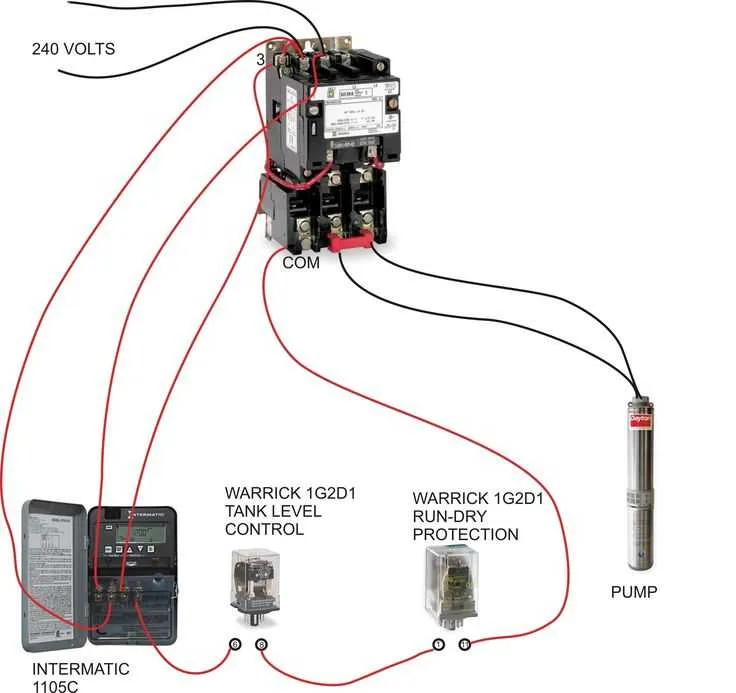
To ensure proper functionality of a high-power water system, follow these steps: connect the motor to a dual-phase power supply, using the appropriate gauge wires for safe current handling. Use a double-pole breaker rated for the motor’s current draw. The system requires a direct connection to the power source, ensuring that both live wires are linked to the motor terminals without mixing ground and neutral wires.
Ensure that the neutral wire is connected securely to the motor’s common terminal. The ground wire should be attached to the motor’s dedicated grounding point, maintaining proper safety standards. For protection against overcurrent, install an overload relay that matches the motor’s specifications, which will cut off the circuit in case of excessive current flow.
Confirm that all connections are tightened properly to prevent voltage drops and potential overheating. The conductors should be rated for the specific load to avoid electrical hazards. A proper electrical conduit or cable sleeve is necessary to shield the wires from environmental damage and provide extra safety. Finally, verify the system using a multimeter to ensure correct voltage at the motor terminals before powering on.
Understanding the Power Requirements for High Voltage Water Systems

Ensure your electrical system is compatible with the specific power demand of your water system to prevent overloading and ensure safety. The motor powering the system typically operates on a dual-phase setup, requiring a strong power supply to function efficiently. Here are key factors to consider:
- Check the amperage requirement of the motor. Most high-power motors will draw 10-20 amps depending on size and output.
- Verify the breaker size. The correct circuit breaker is essential to avoid tripping or fire hazards. Choose a breaker that matches the motor’s amperage draw.
- Confirm the wiring gauge. For optimal performance, use a wire gauge appropriate for the current and distance between the motor and the power source. Typically, 10 to 12 gauge wire is recommended for motors up to 20 amps.
- Ensure proper grounding. A reliable ground connection prevents electrical surges and protects equipment.
Always follow the manufacturer’s specifications when setting up the electrical system to avoid potential damage and ensure efficient operation. If unsure, consult with an electrician to assess power needs based on motor capacity and specific system requirements.
Step-by-Step Process for Connecting a 240V Water Supply System
Ensure the main power is turned off before starting. Use a multimeter to confirm the circuit is not live.
Install an appropriately rated circuit breaker to the electrical panel. The breaker should match the amperage of the motor, typically between 15-30 amps depending on the model.
Run the power cables from the electrical panel to the connection point near the equipment. Choose cables with adequate insulation to handle the system’s current load.
Connect the ground wire to the grounding bar in the electrical panel. This is crucial to ensure safety in case of a fault.
At the equipment, connect the two hot wires from the power cables to the designated terminals on the control box or motor starter. Make sure the connections are secure and tightened properly to avoid arcing.
The neutral wire should be connected to the neutral terminal, if applicable. This step depends on the specific equipment requirements and configuration.
Check all connections for tightness and proper placement. Ensure that there are no exposed wires or loose terminals that could pose a risk.
Before powering up, verify the system’s wiring layout against the manufacturer’s guidelines to ensure it matches the recommended setup.
Once the connections are confirmed, flip the circuit breaker on. Use a voltmeter to check the output voltage at the motor terminals to ensure proper functionality.
If the system operates as expected, proceed to test it under load to confirm stability. Listen for unusual sounds or vibrations that may indicate issues with the setup.
Always double-check that the ground connection is functioning properly and that the motor does not overheat after extended operation.
Common Electrical Issues and Troubleshooting for High-Power Submersible Units
Ensure all connections are tight and free from corrosion. A loose or corroded connection can lead to voltage drops, preventing proper operation. Check terminal blocks and connectors for signs of damage.
If the unit doesn’t start, inspect the capacitor. A faulty capacitor can prevent the motor from starting or cause it to run inefficiently. Test it using a multimeter for continuity, or replace it if there are signs of failure.
Examine the circuit breaker and fuse for continuity. If either component is faulty, the system won’t receive power. Replace any blown fuses or reset tripped breakers before proceeding.
Verify the power supply voltage matches the system’s specifications. If the electrical input is too high or too low, it could cause the motor to malfunction. Use a voltmeter to check the incoming voltage at the terminal block.
Check for wiring shorts between the motor leads and ground. If there’s a short, the system will not operate and could be damaged further. Look for exposed wires or signs of wear in the cable insulation.
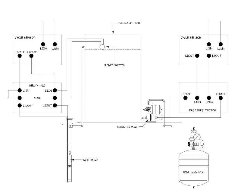
Inspect the control switch. A faulty pressure switch or relay can prevent the system from engaging or turning off correctly. Test the switch’s functionality and replace it if necessary.
Test the motor with a multimeter to ensure it’s not shorted or grounded. If the resistance is too low or the windings show a short, the motor may need to be replaced.
If the system runs intermittently, look for signs of overload or faulty electrical components. The motor may be drawing excessive current due to a malfunction in the motor winding or other parts. Use an ammeter to measure the current draw and compare it to manufacturer specifications.