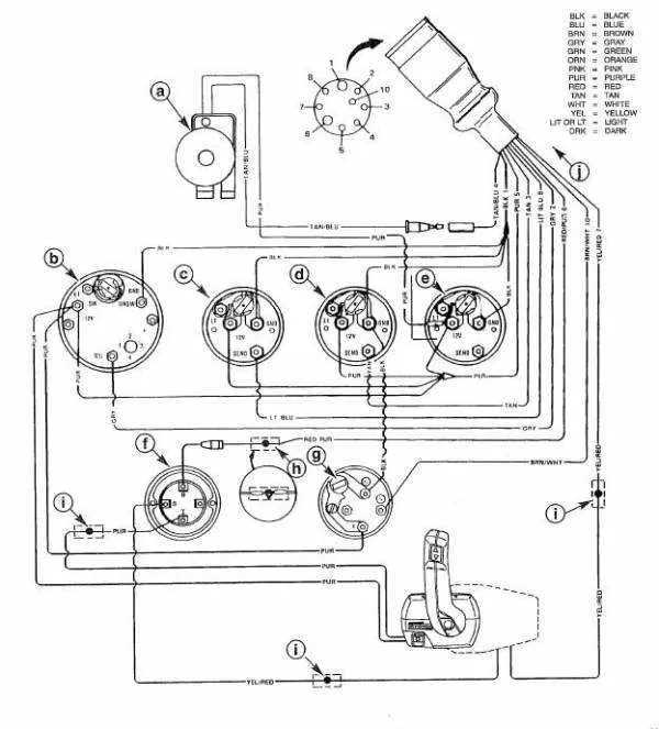
To ensure optimal performance of your boat engine, it’s crucial to follow the correct connection scheme for its electrical components. Without a proper layout, power loss, malfunctioning of critical systems, and even potential damage to the engine can occur. Start by referencing the detailed connection map that corresponds with your specific engine model.
Always double-check the color codes and terminals when connecting the power source to the ignition system. Pay close attention to the grounding points, as improper grounding can lead to erratic engine behavior or complete failure. Verify all wire connections for tightness and security, as loose contacts are a common cause of electrical issues.
When handling the wiring, ensure the correct gauge and insulation type for each wire, especially those linked to high-current components like the starter motor or fuel pumps. Any incorrect wiring can trigger short circuits or component overheating, leading to costly repairs. Adherence to manufacturer specifications is key in avoiding these risks.
Electrical Setup and Troubleshooting
When working on the power unit’s electrical system, follow these guidelines to ensure proper connections and smooth operation.
- Always begin by disconnecting the battery before working on any electrical parts to avoid short circuits.
- Check the ignition system and ensure the correct polarity for all terminals to avoid potential issues with starting.
- If dealing with a non-starting engine, inspect the fuse box and replace any blown fuses with the correct amperage ratings.
- Ensure all grounding connections are clean and free of corrosion to maintain proper electrical flow.
For accurate troubleshooting, use a multimeter to measure voltage at key points such as the starter motor and ignition switch. It’s crucial to check for continuity in all wires and cables to avoid unnecessary part replacements.
- Test the stator by measuring the resistance between the stator leads and the engine ground.
- Inspect the rectifier/regulator to ensure it’s correctly converting AC power to DC, and check for overheating issues.
For efficient diagnostics, refer to manufacturer-specific manuals or schematics to confirm proper wire routing and connections, as each model may vary slightly. This ensures all components are connected correctly and safely.
Understanding Key Wiring Components for Marine Engines
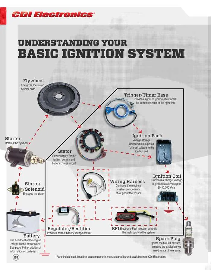
Start with the ignition system: The ignition switch connects to the primary coil, responsible for sparking the engine. Ensure that the coil’s ground is properly connected to avoid misfires or failure to start. If your motor uses a CDI (Capacitor Discharge Ignition) system, check the connection to the stator and ensure it delivers proper voltage to the ignition module. A loose or corroded connection here can cause intermittent issues with engine starting or stalling.
Fuel system connections: The fuel pump relay is a critical component that controls fuel delivery. Verify the relay’s function by testing the voltage at the fuel pump terminals. Ensure the relay is receiving proper signals from the control unit, as a malfunction can result in poor fuel pressure and engine performance problems. Always check that the fuel pump is grounded securely to prevent electrical fluctuations.
Power supply to electronics: Make sure the battery terminals are clean and corrosion-free. A weak or intermittent power supply to the control unit can cause malfunction in sensors, resulting in miscommunication between components. Check the voltage regulator and rectifier to ensure they are regulating the electrical flow correctly; if not, replace them to prevent damage to the system.
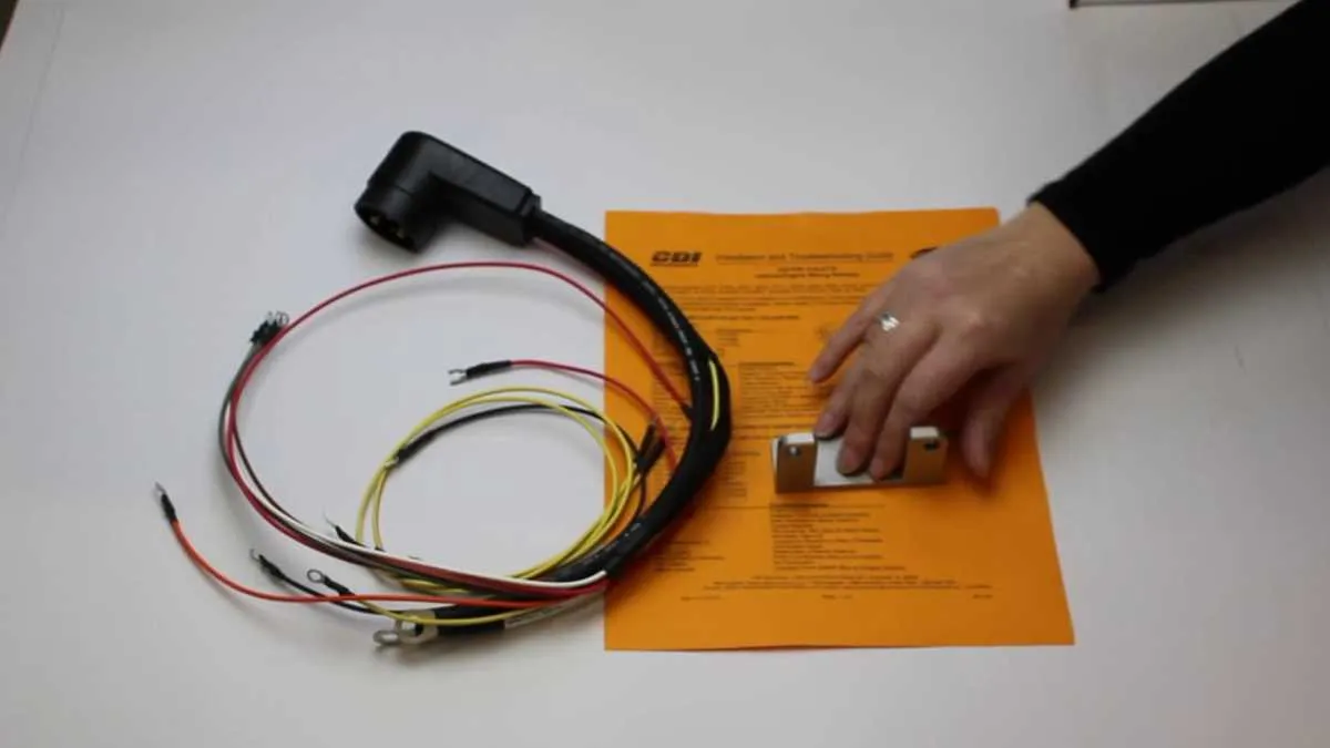
Wiring harnesses and connectors: Inspect all connectors for signs of wear, corrosion, or damage. Pay special attention to the main connector that links the electrical components to the power supply. Damaged or corroded connectors can lead to power losses, creating issues that can be difficult to trace without thorough inspection. Ensure all harnesses are secured and routed away from hot surfaces to prevent wear and overheating.
Step-by-Step Guide to Wiring Ignition Systems for Marine Engines

Start by disconnecting the battery to prevent any electrical shorts or shocks during installation. Ensure all components are clean and dry before proceeding.
Locate the ignition switch and connect the primary lead to the switch’s terminal. This will serve as the central point for the ignition circuit.
Next, connect the magneto or alternator’s output wire to the ignition coil. This wire will carry the power needed to produce a spark at the engine’s spark plug.
Attach the spark plug wires to their respective terminals on the ignition coil. Ensure that each wire is securely fastened and free from damage. Each wire should be routed carefully to avoid wear or short-circuiting.
Connect the kill switch to the ground terminal. This is a crucial safety feature, as it will cut the power in the event of an emergency.
After connecting all necessary components, check the wiring for any loose connections or exposed wires. Use insulated connectors to secure all connections and protect against corrosion.
Finally, reconnect the battery and test the ignition system by turning the key. If the engine fails to start, recheck each connection and ensure that the ignition coil is functioning properly.
Troubleshooting Common Electrical Problems in Marine Engines

Start by checking the fuse and circuit breakers to ensure they’re intact. If there’s no power, replace blown fuses and reset any tripped breakers. Verify that the battery is fully charged and the terminals are clean and properly tightened. Corroded or loose connections can cause intermittent or no power. Inspect the battery cables for any visible signs of wear or damage. If necessary, replace damaged cables to restore a secure connection.
If the engine won’t start, test the starter motor using a multimeter. A malfunctioning starter can prevent ignition. Check the kill switch and safety lanyard, as these components can interrupt power if they are faulty or disconnected. Ensure the ignition switch is functioning by testing continuity with a multimeter. Faulty switches can prevent the engine from starting altogether.
For any unusual performance, test the alternator output using a voltmeter. A weak alternator can fail to charge the battery, causing power issues. Check all grounds to make sure they’re securely attached to clean, unpainted metal surfaces. Poor grounding can lead to electrical malfunctions, including erratic engine behavior and failure to start.