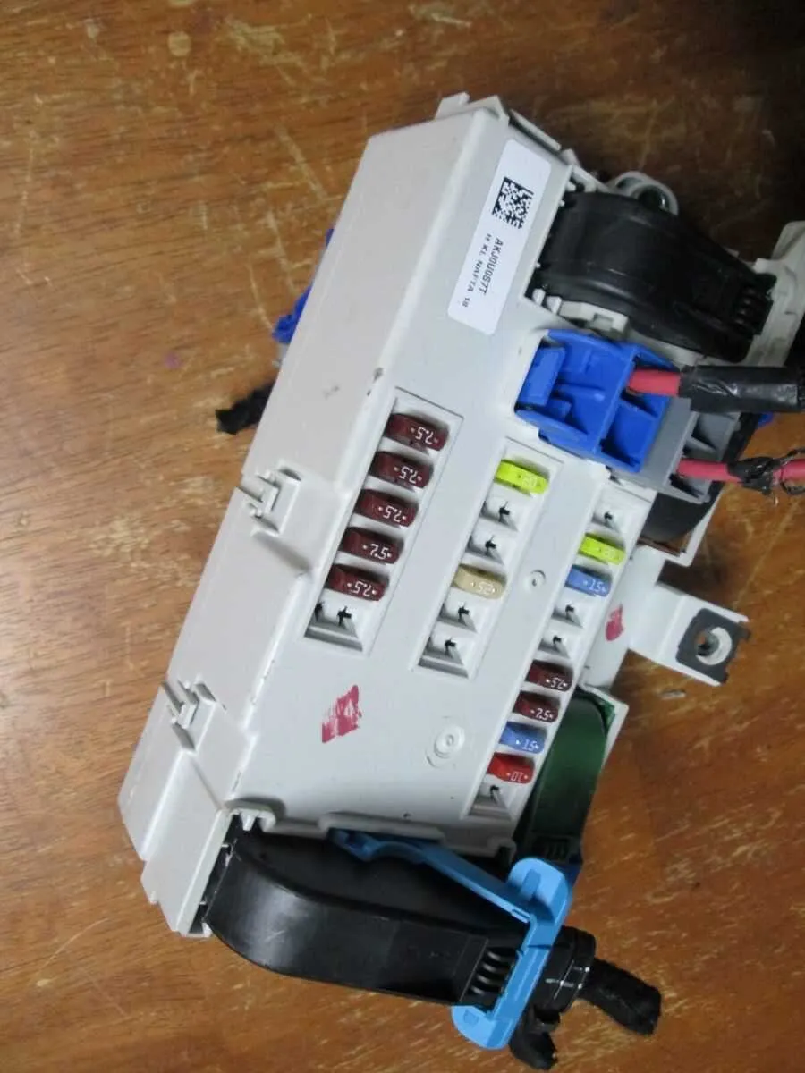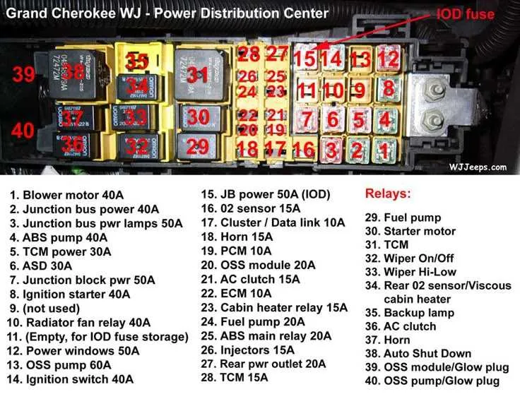
To identify the location and function of each electrical component within the vehicle’s control system, it is crucial to familiarize yourself with the organized arrangement of the circuits. This will guide you in troubleshooting issues and making necessary adjustments with precision.
Understanding the allocation of relays, connectors, and protection elements is essential for maintaining the vehicle’s optimal performance. Each section has a distinct role in distributing power to vital systems like lighting, ignition, and the entertainment console. Proper inspection of the connections can prevent overloads and electrical failures.
Key steps to follow include consulting the vehicle’s reference guide for a clear map of components, followed by verifying the integrity of each unit. Make sure to examine both primary and secondary connection points to avoid misidentifications.
For those with advanced troubleshooting needs, detailed layouts allow for pinpoint accuracy when diagnosing and replacing faulty elements. Should you encounter issues with specific circuits, carefully inspect each terminal for wear or corrosion to ensure an effective repair.
Electrical Component Placement and Configuration
For proper troubleshooting and maintenance, it’s essential to locate and identify the correct modules controlling the vehicle’s electrical system. Below are the main locations and functions of key relays and circuits:
- Engine Compartment Module: Houses critical power systems. Check the left side for high-voltage components like the starter relay and air conditioning controls.
- Cabin Control Unit: Located beneath the dashboard. This unit governs cabin accessories, including lighting, wipers, and seat heating elements.
- Power Distribution Relay Area: Positioned near the engine compartment’s primary power circuit. This section regulates power flow to vital systems like the ignition and fuel delivery components.
Ensure to inspect these areas regularly for any blown connections or damaged terminals. Regular inspection will prevent system malfunctions and ensure a smooth ride.
Identifying Component Locations in the Electrical Panel
To locate the necessary electrical connections, first refer to the panel layout, which outlines each circuit’s position. Start by finding the main panel inside the cabin, typically on the driver’s side under the dashboard or near the footwell area. Once located, use the reference map to pinpoint each specific component.
1. Power Distribution: The main circuits controlling essential functions like headlights, air conditioning, and power windows are usually situated in the center or upper portion of the panel. Make sure to check these areas first if you’re troubleshooting electrical faults in these systems.
2. Auxiliary Components: For less critical circuits, such as those powering the interior lights or certain infotainment elements, look for the lower sections. These are typically closer to the panel’s edges, and the fuses controlling them are often grouped by type or function.
3. Color Coding: Many panels use color-coded indicators to make identification easier. For example, red often corresponds to high-powered circuits, while green might be used for smaller, low-power components. Understanding this coding system can save valuable time when addressing electrical issues.
Note: Always ensure the ignition is off before manipulating the electrical panel to avoid accidental short circuits or injury.
How to Replace a Blown Fuse in Your Vehicle

To replace a malfunctioning component, start by locating the electrical panel, usually found under the dashboard or in the engine compartment. Refer to the vehicle’s manual to pinpoint the correct area. Once identified, open the panel and inspect the components for damage or signs of wear.
Use a fuse puller or a pair of insulated pliers to remove the damaged part. Be sure to handle the component carefully to avoid any contact with metal parts that may cause a short circuit. Check the component for any visible signs of damage, such as a broken metal filament.
Insert a replacement component that matches the required amperage, typically indicated on the back of the panel or the owner’s manual. Using the correct type ensures safe operation and prevents further electrical issues. Press the new part into place, ensuring it fits snugly within the designated slot.
After replacing, turn on the vehicle and test the circuit. Ensure that the newly installed component restores the functionality of the affected system. If the problem persists, verify the installation or consult a professional to check for deeper electrical issues.
Understanding Component Protection Ratings
Ensure each electrical part is safeguarded by selecting the appropriate protection value. For circuits managing low-power components like lights, use low-rating protection, typically around 10A. Higher-powered systems such as air conditioning units or engine management require protection of 30A or higher, depending on the power draw. Always check component manuals for recommended protection levels.
The protection device chosen must match the current flow the component requires to function properly. Too low a rating may cause frequent interruptions, while too high a rating can fail to protect the circuit effectively during a fault.
For components like the power windows or seat adjustments, a 20A protection is commonly sufficient, but verify with the manufacturer for specific requirements. Additionally, if any device is modified or upgraded, reassess the protection values to match the new specifications and prevent damage from overloads.
Ensure that all replacements use the same specifications for rated protection, as using incorrect values may compromise system reliability and safety.