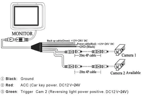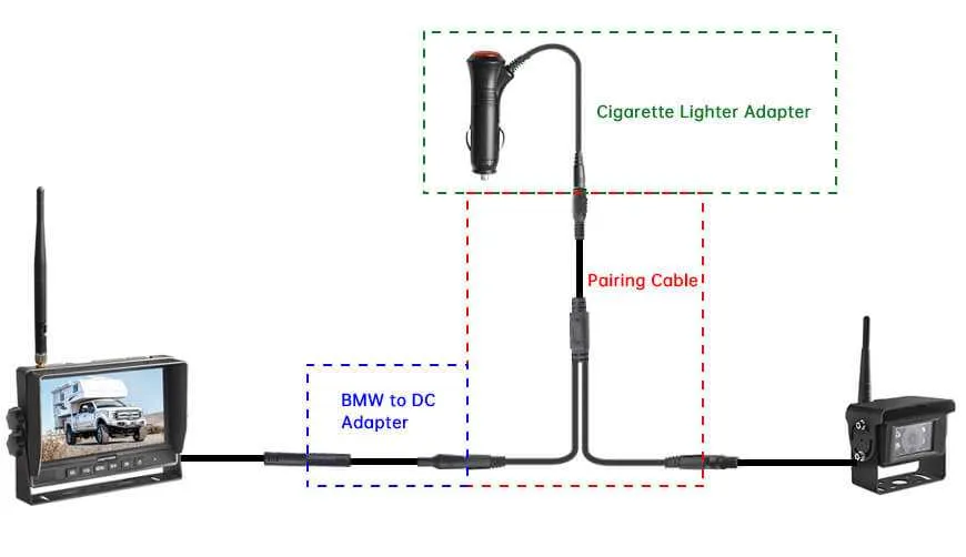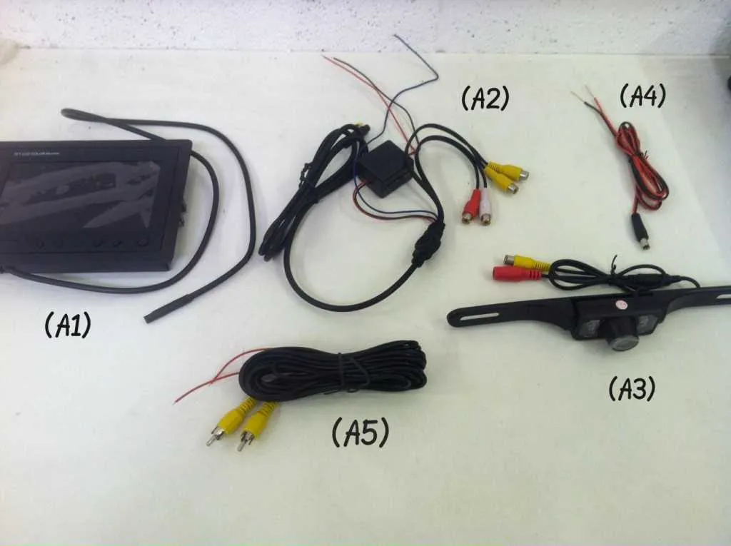
To ensure optimal installation of your backup system, first locate the power supply that will be connected to the system’s interface. It is crucial to tap into the vehicle’s reversing lights circuit. This will provide the necessary signal to activate the unit when shifting to reverse gear.
Next, identify the appropriate ground connection to complete the electrical circuit. The best practice is to use a clean, bare metal point near the installation site for reliable grounding. For optimal signal quality, ensure all connections are secure and free from corrosion.
Once the power and ground are in place, the video transmission wire must be routed from the system’s display to the rear section of the vehicle. Use high-quality shielded cable to avoid signal interference, ensuring clear visuals when reversing.
Additional Tip: Make sure the interface unit is connected to the reversing signal so that it only activates when the vehicle is in reverse, saving power and enhancing longevity. Proper insulation and careful wire placement are key to preventing any damage from moisture or heat exposure.
Note: Following these steps will result in a reliable installation, enhancing safety and providing a seamless experience while reversing.
Installing the Backup Monitor System

Connect the power lead from the monitoring device to the vehicle’s reverse light circuit. This allows the monitor to turn on automatically when shifting into reverse gear. Ensure the ground wire is securely attached to the car chassis for proper functionality.
The signal transmission between the monitor and the display unit must be done using a coaxial cable. Use high-quality, shielded cables to minimize interference and ensure clear image quality. The signal wire should be routed safely, away from any moving parts or sources of heat, such as the exhaust system.
The lens module should be installed on the vehicle’s rear section, typically above the license plate area. Ensure that the mounting location allows for optimal coverage of the area behind the vehicle, while avoiding any obstructions. Use screws or brackets to firmly secure the unit, and avoid over-tightening to prevent damage.
Connect the video signal wire to the monitor’s input terminal. Check that the connection is tight and free from corrosion to prevent signal loss. The power lead from the lens unit should be routed to the reverse light power supply to activate the device only when the vehicle is in reverse gear.
For safety, use a fuse in the power line to protect the system from electrical surges. This will help prevent damage to both the monitoring device and the vehicle’s electrical components.
How to Connect a Backup System to a Car’s Power Supply

Start by identifying the power source. You will need to tap into the vehicle’s reverse light circuit, as it supplies power when the car is in reverse. Cut the positive wire of the reverse light and connect it to the positive input of your backup system’s power input. For grounding, locate a suitable bolt on the car’s chassis to attach the ground wire of the system.
Step 1: Remove the car’s rear light assembly to access the wiring of the reverse lights. Use a multimeter to confirm the voltage when the vehicle is in reverse to ensure you’re tapping into the correct wire.
Step 2: Once identified, strip the reverse light wire and attach a quick splice connector to securely join it with the power cable of the backup system. This will allow the system to be powered only when the car is in reverse.
Step 3: Connect the ground wire of the system to a metal part of the car’s body. It’s crucial to ensure a clean and secure connection to avoid interference or malfunctions.
Step 4: Once all connections are in place, test the system by putting the car in reverse. The system should power on and be ready to use. Ensure that the system turns off when the vehicle is out of reverse.
Tip: If the system requires a constant power source, you can also connect it to the vehicle’s fuse box, ensuring you use the appropriate fuse type to prevent any electrical issues.
Choosing the Right Wiring for Signal Transmission
For optimal signal performance, use high-quality coaxial cables with a shielding layer to reduce interference. Shielded cables are ideal for maintaining clarity and preventing distortion over long distances, especially in vehicles where electromagnetic interference (EMI) is common.
Choose cables with a low resistance to ensure consistent signal strength. Copper wires provide better conductivity than aluminum and are recommended for minimal signal loss.
When selecting connectors, opt for waterproof options to avoid corrosion and ensure longevity. These connectors maintain a secure connection and prevent water damage, which is crucial for outdoor installations.
Ensure the selected cable has the appropriate gauge for the distance it will cover. For longer runs, thicker cables (such as 18 AWG or 16 AWG) help reduce signal degradation. For shorter distances, thinner cables (20 AWG) may suffice, but thicker ones are generally more durable and efficient.
For installations with high-resolution systems, prioritize cables that support higher frequencies to maintain image quality. Cables designed for high-bandwidth applications ensure the transmission remains crisp and clear, especially for advanced systems requiring higher data rates.
Consider using twisted pair cables for power transmission to minimize voltage drop and avoid signal distortion from adjacent power lines.
Lastly, ensure proper grounding to prevent electrical noise and ensure stable signal transmission, especially when dealing with systems that require precision and reliability.
Step-by-Step Guide to Proper Grounding in Backup System Installations
Start by selecting an appropriate grounding point. Ideally, this should be a clean, metal surface on the vehicle’s chassis, free from rust or paint to ensure a solid connection.
- Locate a bolt or screw that connects directly to the metal frame.
- If no suitable point exists, you may need to create one by using a self-tapping screw or ground wire terminal.
When connecting the ground wire, use a ring terminal for a secure, tight fit to the grounding point. A loose or improper connection can cause electrical interference and unreliable system performance.
- Ensure the ground wire is as short as possible to minimize resistance.
- If extending the wire, use a high-quality gauge that matches the system’s requirements to avoid voltage drops.
Before finalizing the installation, verify the connection by testing the system’s functionality. A poor ground connection may lead to flickering or distorted signals.
If issues arise during testing, check the ground again. Use a multimeter to test continuity between the ground connection and the chassis to ensure a stable link.