When wiring a trailer, ensure that the correct wiring configuration is followed to avoid electrical issues. Use a 7-pin connector for standard trailer connections, which covers most vehicles and trailer setups. This type of connection provides all the necessary signals for the trailer’s lights, brakes, and other electrical functions.
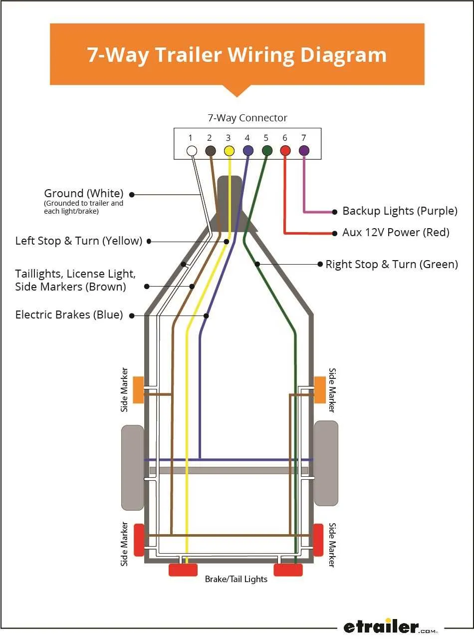
For proper installation, match the vehicle’s wiring to the corresponding pins in the connector. Typically, the white wire is for ground, the yellow and green wires for left and right turn signals, respectively. The red wire is for the brake lights, while the brown wire is used for tail lights. Always check the vehicle manufacturer’s instructions to ensure correct pin assignments.
Before starting, make sure the wiring is securely connected and free from any potential wear or damage. Use high-quality connectors that are designed for outdoor use to prevent corrosion, ensuring long-lasting functionality. Test all lights and functions before hitting the road to verify proper connection and safety.
Wiring Scheme for Trailer Connection
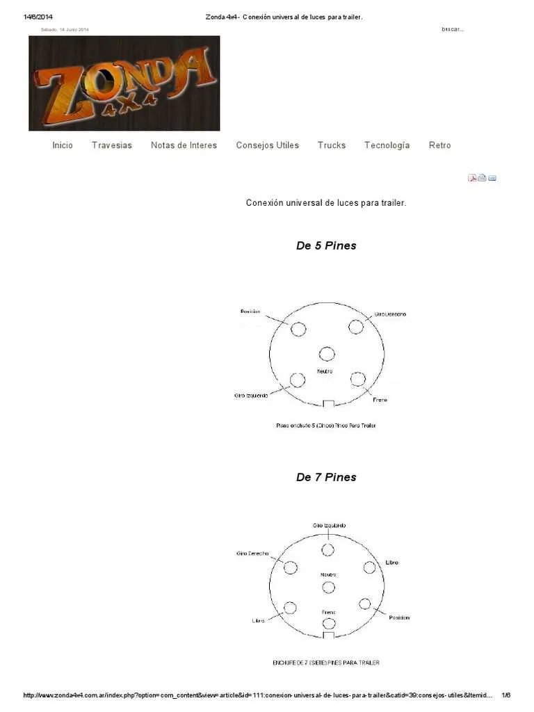
Ensure proper wiring when connecting your vehicle to the trailer. Each pin on the electrical plug serves a specific function. Make sure the ground connection is secure, as it’s essential for stable signal transmission. The vehicle side typically uses a 7-pin setup, with a few variations depending on the region or specific use case.
For a 7-pin configuration, the pins are usually mapped as follows: Pin 1 is reserved for the ground connection, Pin 2 for left turn and brake light, Pin 3 for right turn and brake light, Pin 4 for tail lights, Pin 5 for reverse lights, Pin 6 for electric brakes, and Pin 7 for auxiliary power or additional signals.
Verify the wiring on both ends before use to avoid damage to your trailer’s lights or electrical systems. It’s crucial to use high-quality connectors to minimize wear over time, especially if you frequently connect and disconnect the trailer. Always inspect the integrity of the wires and ensure no exposed wires are at risk of short-circuiting.
If you’re retrofitting an older trailer or vehicle, consider upgrading the connection to match modern standards, as this can prevent issues related to voltage drops or incompatible signals between vehicle and trailer systems.
How to Read a Trailer Wiring Diagram
Start by identifying the pinout configuration, which defines how each terminal corresponds to different functions. A proper understanding of the wire color code and terminal locations is crucial for connecting components accurately.
Follow these steps to read and interpret the diagram:
- Identify the wire functions: Typically, wires are color-coded to represent specific functions like ground, left turn signal, right turn signal, brake light, and others. Ensure you match the color to the correct terminal.
- Understand the pin numbering: Each terminal is usually numbered. This number is used to identify the corresponding connection on the trailer plug or the towing vehicle’s harness.
- Check for any additional markers: Some diagrams include labels or symbols to clarify the function of each wire. Pay attention to these indicators for better understanding.
- Verify the grounding wire: The ground connection is crucial for proper functionality. It is commonly shown as a black or white wire and should always be connected securely to the chassis or the vehicle’s frame.
Once you know the wire functions and terminal locations, cross-check them with the actual connections on the trailer and vehicle. This ensures that each component is correctly wired and eliminates potential issues like mismatched signals.
Identifying Common Trailer Wiring Issues in the Diagram
Start by checking for loose or disconnected wires. If the lights, brakes, or turn signals aren’t functioning, inspect the connections for any visible gaps. Ensure each wire is securely attached to its terminal, especially for the ground connection, as poor grounding is a frequent cause of electrical failures.
Corrosion is another common issue. When exposed to moisture, metal connectors can rust, leading to faulty circuits. Look for greenish discoloration or a buildup of rust around the pins and sockets. Cleaning these with a wire brush or contact cleaner can restore functionality.
Pay attention to the wire gauge used. Inadequate wire thickness can cause power loss, especially for high-current circuits like brake lights or tail lamps. Compare the wire gauge with the specifications outlined for your trailer’s electrical system.
Lastly, check for damaged or frayed wires. Wires that have been scraped or pinched can result in short circuits or intermittent failures. Replace any damaged wires immediately to avoid further electrical issues.
Step-by-Step Guide to Wiring a Trailer Based on the Diagram

Start by identifying the correct pinout for your trailer’s wiring system. Make sure you have the appropriate connectors and a reliable power source before proceeding.
1. Connect the white wire to the ground terminal on the vehicle’s socket. This is the most critical step as it ensures proper functioning of all electrical components.
2. Attach the yellow wire to the left turn signal and brake light terminal. This wire controls the left-side indicators and the brake lights when activated.
3. The green wire should be connected to the right turn signal and brake light terminal. This will handle the right-side indicator and brake light functions.
4. For the running lights, use the brown wire. Connect it to the corresponding terminal that powers the trailer’s lights, ensuring that the trailer’s rear lights remain lit when the vehicle’s lights are on.
5. Finally, connect the blue wire to the brake controller on the vehicle, ensuring it controls the trailer’s brakes during operation.
Double-check all connections for secure contact and proper insulation to prevent short circuits. Once wiring is complete, test all functions–left and right turn signals, brake lights, and running lights–before use.