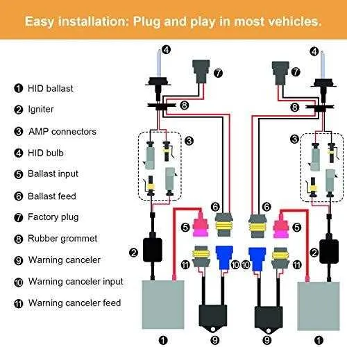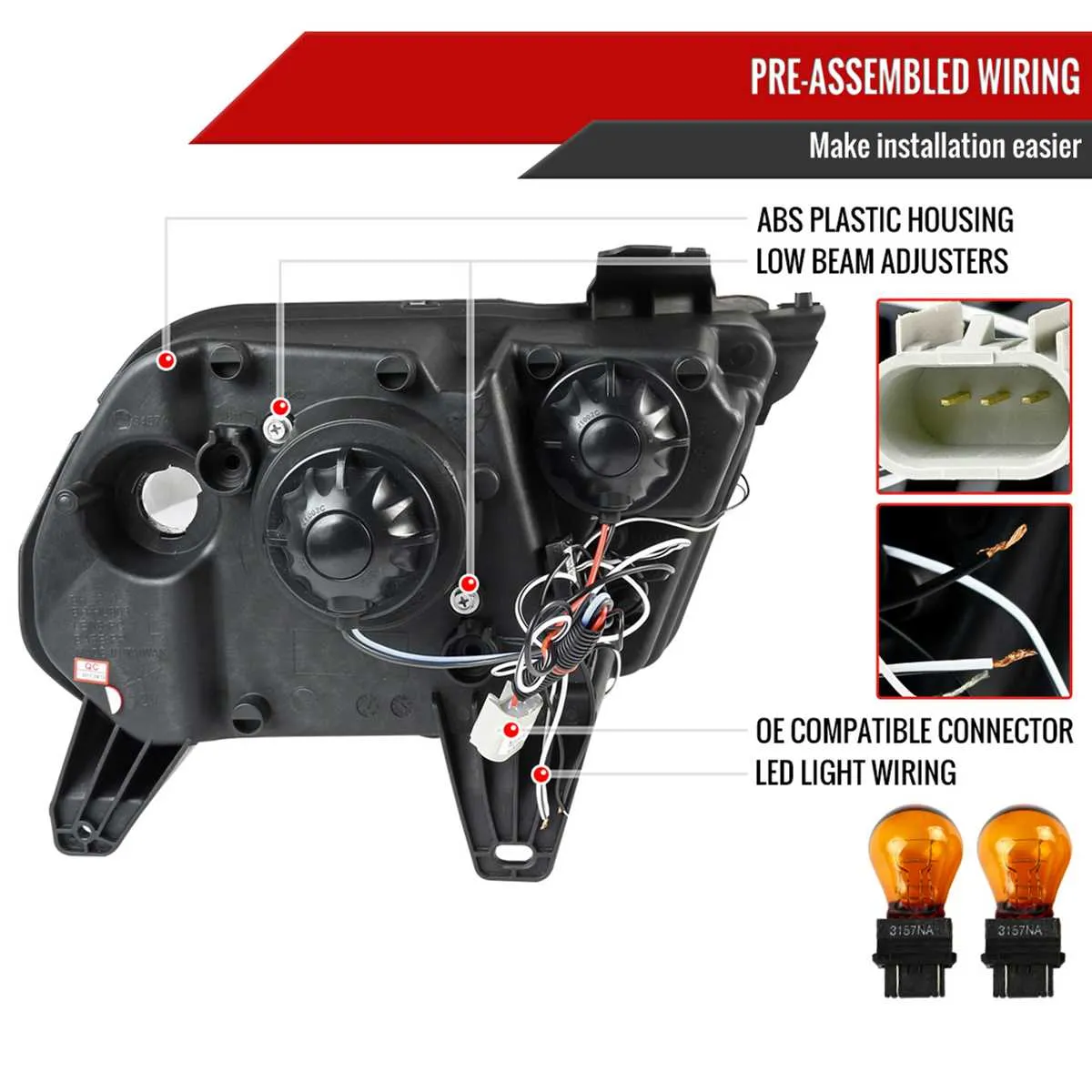
For efficient and safe installation of your xenon lamps, ensure the connections are secure and correctly routed. The primary power source should be carefully connected to the ballast, which then powers the bulbs. Follow the wiring instructions step-by-step, starting with the positive terminal leading directly to the ballast. Make sure the ground wire is attached securely to the vehicle’s chassis to avoid electrical faults.
Important steps: The power cables from the ballast must be routed through the appropriate conduits to prevent exposure to external elements. Double-check that no wires are under tension, as this can lead to short circuits over time. Use appropriate connectors to ensure proper fit and longevity of the electrical system. Pay special attention to fuse placement to protect your lighting system from electrical surges.
Pro tip: Test the system for continuity and functionality before fully assembling all components. If any irregularities arise during testing, investigate the ballast and its connection to the electrical system first.
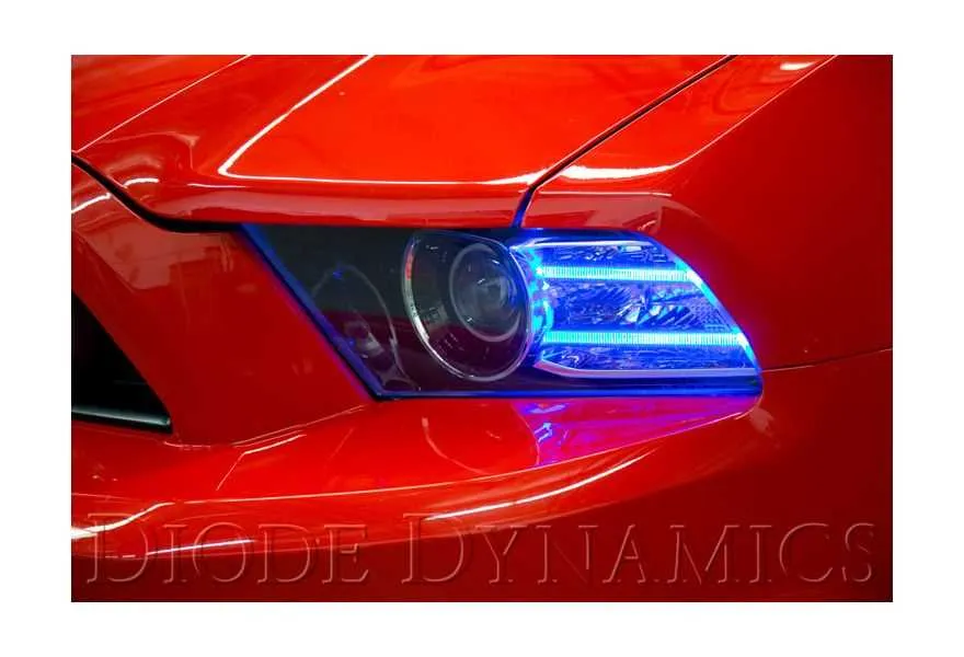
Wiring Setup for Xenon Lights in a 2014 Muscle Car

For proper installation of high-intensity discharge (HID) lighting systems in your vehicle, it’s critical to follow a correct connection pattern to ensure reliable performance and longevity. Start by identifying the power input from the main electrical circuit, then connect it securely to the ballast, which regulates the voltage. The next step is linking the ballast to the lighting units using the output cables, ensuring the connectors are sealed to prevent moisture damage. Use high-quality, insulated cables to minimize the risk of short circuits.
Ensure all connections are tight and free of corrosion. A relay should be incorporated into the setup to manage the electrical load, providing additional protection to the car’s electrical system. The relay should be placed between the power source and the ballast for maximum efficiency. Pay attention to the polarity of the connections; incorrect wiring can result in malfunctioning lights or even damage to the system components.
For advanced systems that require control over light intensity, include a dedicated switch or adjuster to modulate power. Use fuses rated for the system’s power requirements to protect the circuits from overloads or sudden spikes in current.
Once everything is connected, test the system by powering it on and checking the output from the lights. If there is flickering or dim output, double-check the connections, and ensure the ballast is properly grounded. Regular maintenance and cleaning of connectors and components will extend the lifespan of the setup.
Understanding the Basic Wiring Layout for Xenon Lamps
Ensure proper connection of the ballast to the vehicle’s electrical system, paying special attention to polarity to avoid damaging components. The ballast should be linked to the vehicle’s power supply, with an additional connection to the lamp for proper functioning.
Below is a general overview of the components involved in the electrical setup, including connections to the lamp unit and ground wire:
| Component | Description | Connection Points |
|---|---|---|
| Ballast | Regulates the electrical current to the lamp | Connected to power supply and lamp unit |
| Power Supply | Provides electrical power to the ballast | Direct connection to the vehicle’s battery or fuse box |
| Lamp Unit | Converts electrical energy into light | Connected to ballast and ground |
| Ground Wire | Ensures safe discharge of electrical current | Connected to vehicle chassis |
When installing, always check that the ballast is securely mounted and the connections are firm to prevent any electrical failure or malfunction. Proper insulation and weatherproofing are also critical to avoid short circuits due to exposure to the elements.
How to Identify the Correct Wires for Installation

To ensure proper connection, follow these steps to pinpoint the right cables for your installation:
- Consult the Vehicle Manual: Always refer to the specific guide or manual that outlines the color codes and function of each cable in your car’s electrical system.
- Use a Multimeter: Verify the function of each wire using a multimeter. This tool will help you identify live wires, ground connections, and signal paths.
- Check the Connector Type: Ensure that connectors match correctly with the harnesses you are working with. Different systems may use specific connector types, which are key to proper installation.
- Color Coding: Pay close attention to the color of the cables. Typically, red is used for positive power, black for ground, and other colors indicate specific functions like control signals.
- Verify the Voltage: Double-check the voltage specifications for each wire. Some systems may require 12V while others may need a lower or higher voltage for specific functions.
By following these steps, you can confidently identify and connect the necessary wires for your installation project. Ensure each wire is properly insulated and protected to prevent shorts or electrical failures.
Common Wiring Issues and Troubleshooting Tips
Check for loose connections in the electrical system, especially at the power supply and ballast. Loose connections can result in intermittent light function or complete failure. Make sure all connectors are firmly seated and locked in place.
If the lights flicker or turn off unexpectedly, inspect the grounding connections. A poor ground can cause voltage fluctuations that disrupt the system’s operation. Ensure that the ground is clean, secure, and properly connected to the vehicle chassis.
Corroded terminals are another common issue. Examine each terminal for signs of corrosion or damage, particularly where connectors meet the power source. Clean and replace corroded components to ensure optimal conductivity.
Fuse failure is often a symptom of an overload in the circuit. If your system fails to operate after checking the connectors and grounding, inspect the fuse for any visible damage or breakage. Replace it with the correct amperage rating to avoid further issues.
Sometimes, damaged cables can lead to short circuits, especially in areas that experience frequent movement or pressure. Inspect the cables for wear or cuts, and replace any sections that show signs of damage.
In cases where the system is not turning on at all, consider testing the control module. If the module is faulty, it may prevent the system from receiving power. Diagnosing and replacing the module may resolve the issue.