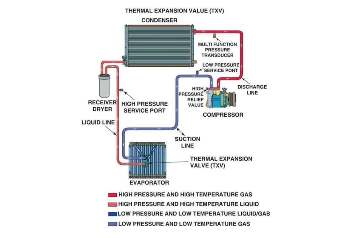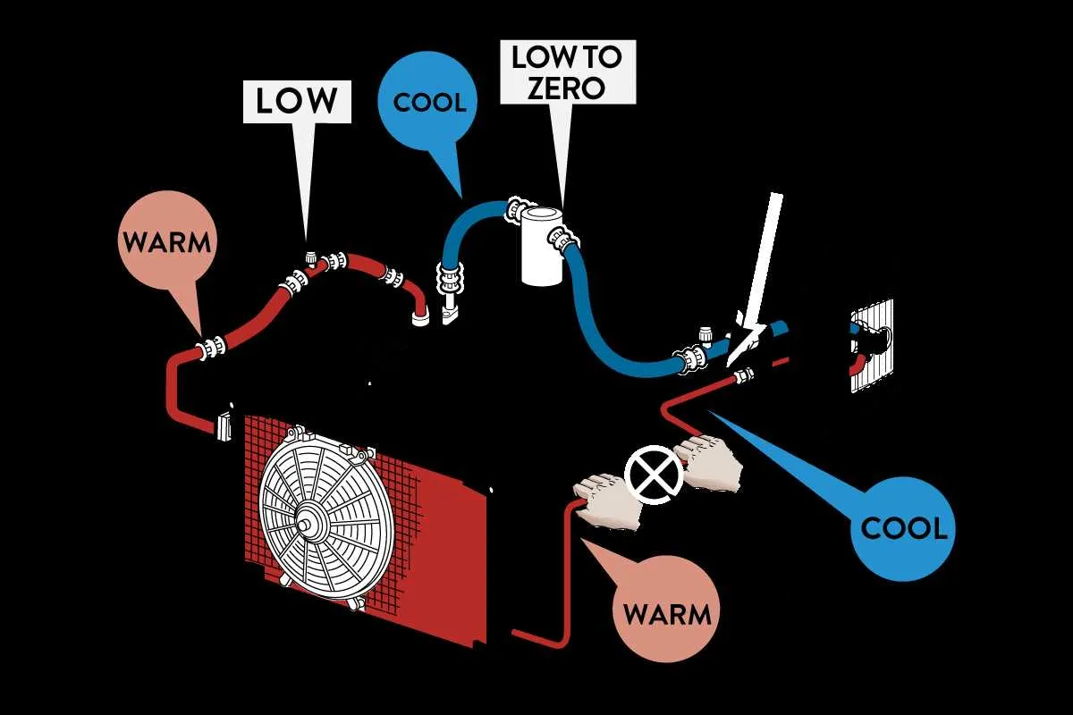
Always position the metering device between the condenser and the evaporator to ensure optimal pressure regulation. This narrowing passage is responsible for transforming high-pressure liquid refrigerant into a low-pressure mist, which improves heat absorption inside the cabin.
Use color-coded schematics to identify components: the expansion passage is often represented near the inlet of the evaporator, while the accumulator, when present, follows it on the low-pressure side. In heat-only or rear-seat cooling configurations, this narrowing component may appear in multiple branches.
Pay attention to the mesh filter on the inlet side. If debris or oil sludge accumulates there, it can block refrigerant flow, leading to poor cooling. Regular inspection and flushing of the fluid lines are recommended, especially after compressor failure or desiccant breakdown.
For retrofitting or diagnosing, observe the temperature differential before and after the restriction point. A noticeable drop indicates correct misting. If both sides are nearly equal, the constriction could be clogged, or there’s insufficient charge in the refrigerant circuit.
Orifice Tube AC System Diagram
Always identify the fixed metering component between the condenser and evaporator, typically located in the liquid line near the evaporator inlet. Its primary role is to regulate refrigerant flow by creating a pressure drop, enabling the conversion from high-pressure liquid to low-pressure vapor.
Trace the refrigerant pathway beginning at the compressor, which sends high-pressure vapor to the condenser. From there, the condensed refrigerant travels through the liquid line, passing through the metering device, then enters the evaporator where it absorbs heat.
Pay attention to the expansion point: this is where the restriction causes rapid cooling. This segment usually contains a mesh filter to trap debris. Debris accumulation in this area can cause inadequate cooling or system imbalance. Check this component for blockages during diagnostics.
Downstream, the accumulator (in most setups using this configuration) ensures that liquid refrigerant does not return to the compressor, safeguarding against damage. Proper oil circulation is also critical; insufficient lubrication can cause premature compressor wear.
Verify sensor placement near the evaporator outlet to monitor thermal efficiency. This helps regulate clutch cycling and prevents freeze-up. Electrical connectors should be inspected for corrosion or loose terminals, especially around control modules interfacing with the metering unit.
Location and Identification of the Orifice Tube in Automotive AC Systems

Begin by checking the high-pressure liquid conduit running between the condenser and the expansion entry point. The metering insert is typically housed within this aluminum line, often near the connection to the evaporator inlet.
In most front-wheel-drive vehicles, the component is integrated into the narrow metal line on the passenger side of the engine bay. Look for a crimped joint or a service port near this section as a clue to its placement. Some manufacturers position it directly behind the firewall, just before the liquid enters the interior cabin unit.
To identify the part, disconnect the line carefully after evacuating the refrigerant. Inside, you’ll find a small mesh screen structure attached to a color-coded plastic sleeve. The hue (commonly red, green, or blue) indicates flow characteristics specific to the vehicle model.
Use a needle-nose plier or a specialized puller tool to extract the insert. Always inspect the removed part for metal shavings or debris, which could point to compressor wear or contamination in the refrigerant path. Replace it only with a compatible match, verified by part number or vehicle service manual.
Flow Direction and Refrigerant Path Illustrated Step-by-Step
Begin at the compressor outlet where high-pressure vapor exits and travels directly to the heat exchanger located at the front of the vehicle. Ensure all connections are free of obstruction to maintain consistent pressure.
From the condenser’s outlet, the fluid–now a high-pressure liquid–moves toward the metering component. It enters the narrowing channel, which reduces pressure rapidly and initiates phase change into a low-pressure mist. Always verify this junction is clean to avoid blockage.
After pressure drop, the chilled mist enters the evaporator coil inside the cabin area. As it flows through the coil, it absorbs heat from the air surrounding the fins. The low-pressure liquid transforms into gas during this process.
The vapor exits the evaporator and proceeds to the accumulator, which separates any remaining fluid droplets. Ensure the accumulator is properly oriented to prevent liquid from reaching the compressor intake.
Finally, the vapor returns to the suction port of the compressor to repeat the loop. Check that the suction line is fully insulated to reduce heat gain and maximize cooling performance.
Common Failure Points and Pressure Drop Zones in the Diagram
Replace the filter assembly if pressure imbalance appears downstream – this typically signals contamination or clogging within the narrowing section.
- Compressor Discharge Port: High-pressure surges at this junction can indicate excessive thermal load or oil starvation. Inspect seals and internal clearances for wear.
- Narrowing Insert Area: The transition zone where refrigerant velocity spikes is prone to debris accumulation. Monitor for sudden upstream pressure spikes indicating blockage.
- Accumulator Inlet: Insufficient flow or backpressure at this node suggests desiccant breakdown or liquid refrigerant overflow. Replace desiccant packs regularly.
- Evaporator Entry Point: Rapid temperature shift across this section often causes wax or ice formation, leading to uneven cooling. Check for moisture contamination in the refrigerant.
- High-to-Low Pressure Transition: Sharp pressure drop here may result in flash gas formation, causing noise and vibration. Ensure correct charge levels and inspect thermal expansion behavior.
Use differential pressure gauges at the inlet and outlet of each transition zone to detect efficiency losses early. Maintain fluid cleanliness and monitor thermal load distribution to extend component life.