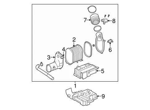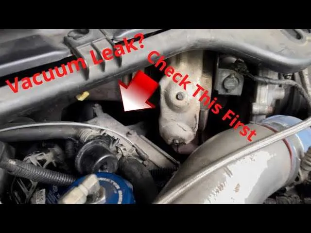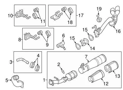
To ensure optimal performance of your engine’s air control mechanisms, it’s essential to have a clear understanding of the key connections in the vacuum network. This system, responsible for operating various components such as brakes, exhaust control valves, and HVAC systems, relies on a network of hoses and connectors. Proper routing of these elements is critical for maintaining efficiency and preventing potential issues such as poor engine performance or malfunctioning accessories.
Check the Routing of Each Hose – The vacuum system operates through a series of tubes and connectors that should follow a precise route. Any deviation or disconnection can result in leaks, reducing system pressure and causing malfunction. Refer to specific service manuals or schematic guides for exact hose placements to avoid mistakes.
Inspect for Leaks – Even minor leaks in the system can lead to a significant drop in overall pressure, causing irregularities in how the engine and connected accessories behave. Regular inspections of the vacuum seals and connections are necessary to ensure they are intact and well-fitted.
Understand the Role of the Control Valve – This part of the system regulates the flow of air to various engine components. Ensuring the valve is correctly positioned and functioning properly is vital for maintaining proper engine control. Misalignment or failure of the valve can lead to irregular pressure in the network, affecting overall performance.
Lastly, always ensure that the components in the system are made from durable materials, resistant to cracking and wear. Routine maintenance and monitoring will help avoid unexpected failures and extend the lifespan of the engine’s critical systems.
Vacuum System Routing for Diesel Engines
To ensure the optimal function of your diesel engine’s air intake and control systems, it is crucial to correctly install and maintain the vacuum hose network. Misrouting or leaks in the hoses can result in poor performance, erratic behavior, and malfunctioning components.
Start by tracing the primary hoses that connect the intake manifold to the actuator units. These should run securely and free from kinks, allowing for proper airflow control. Next, verify the connections to the EGR valve and turbocharger control systems. Any disruption here can significantly affect power delivery and fuel efficiency.
Check the connections at the vacuum pump. This is where the system generates pressure for various functions. Ensure there is no wear or tear on the seals, as air loss will directly impact engine performance. Additionally, inspect the solenoids, as they regulate the flow to critical components like the brake booster and air suspension systems.
Using a pressure tester, confirm that all hoses are sealed properly and that the system maintains the required vacuum levels. If pressure drops unexpectedly, it’s essential to replace damaged or degraded hoses immediately. Be mindful of the routing path for these components to avoid interference with other moving parts or exhaust components.
Identifying Key Components in the Diesel Engine Air Management System

The primary components of this air management system include the pump, solenoids, and check valves. To effectively diagnose issues, start by inspecting the vacuum pump, which generates the necessary pressure to operate critical elements like turbochargers and brake boosters.
Solenoids control the flow direction and are essential for the timing of various system operations. Each solenoid must be tested for continuity and proper voltage. Faulty solenoids often lead to erratic performance or failure to engage specific functions like variable valve timing or EGR systems.
Check valves are used to prevent backflow and maintain consistent pressure. When replacing, ensure that the direction of flow matches the system’s specifications. Incorrect installation can lead to pressure loss and improper system operation.
Inspecting the system requires checking the integrity of all hoses and connections. Any leaks, cracks, or blockages can lead to significant drops in pressure, affecting performance. Pay special attention to connections near the intake manifold, as these are common points of failure.
For thorough diagnostics, use a vacuum gauge to measure pressure levels at different points in the system. This will help identify weak spots or points where pressure may be insufficient. Regular maintenance of these components is crucial for the longevity and efficiency of the engine’s air management system.
How to Trace and Diagnose Airflow System Issues in the 6.4L Diesel Engine
Start by inspecting the routing of all tubes connected to the air control components. A common problem arises from cracks or loose connections that disrupt the airflow. This can lead to malfunctions in systems like turbochargers and the brake booster. To effectively troubleshoot, follow these steps:
- Check for visible damage along the rubber or plastic hoses, especially near bends where they are most likely to crack.
- Use a hand-held vacuum pump to test if any seals are leaking in the intake system.
- Examine connections at the intake manifold for looseness or worn-out gaskets.
- Ensure all clamps are tight and that no parts are misaligned or obstructed.
If the issue is not immediately apparent, proceed with a pressure test. This can help you detect leaks or blockages in hard-to-reach areas.
- Pressurize the system using an air compressor, and monitor any drop in pressure.
- Listen for hissing sounds, which indicate escaping air and potential failure points.
- If a drop in pressure occurs, concentrate on sections with excessive air flow resistance.
Another key diagnostic tool is the system’s diagnostic codes. Many newer vehicles offer error codes related to air distribution. These can point you directly to the problematic components. Make sure to use a scanner to access the on-board computer for codes that may reference air management faults.
- Retrieve DTC (Diagnostic Trouble Codes) from the ECM and cross-reference them with the service manual.
- Focus on codes relating to air pressure, airflow restrictions, or sensor malfunctions.
Ensure that all solenoids and sensors related to airflow are functioning properly. Any failure in these components can cause a system malfunction and affect overall engine performance.
- Test each solenoid using a multimeter for resistance and proper operation.
- Check sensors for corrosion or dirt buildup, which can interfere with their readings.
Finally, always remember to replace any worn-out or damaged components with OEM parts to ensure the system operates correctly over time.
Step-by-Step Guide to Replacing or Repairing Airflow Tubes in a Diesel Engine

Start by identifying the damaged hoses. Inspect each rubber or plastic tube for cracks, leaks, or loose connections. If any are found, it’s crucial to replace or repair them immediately to prevent performance issues.
Next, prepare the necessary tools: a socket set, screwdrivers, clamps, replacement tubes, and sealing tape. Disconnect the battery to avoid electrical short-circuits during the process.
Remove any components blocking access to the affected tubes, such as the air filter housing or engine covers. This will provide more space to work on the system without causing accidental damage to other parts.
Loosen the clamps on the faulty tubes using the appropriate screwdriver or socket. Carefully detach the tubes from their connections without forcing them, as brittle parts can break under pressure.
Cut the new tubing to the appropriate length using a sharp utility knife or tube cutter. Ensure the new tubes match the inner diameter of the existing ones to maintain airflow integrity.
Install the replacement tubes, making sure they are secured tightly to prevent any air leaks. Use fresh clamps to secure the tubes in place, ensuring they are firmly attached but not overtightened to avoid damaging the hoses.
Check for proper fitment and alignment of the new tubes before reassembling the engine. Reconnect any parts that were removed earlier, such as the air filter housing, ensuring everything is aligned and tightened properly.
After reassembly, reconnect the battery and start the engine. Test for leaks by inspecting the new tubes while the engine runs. Listen for any hissing sounds or notice any changes in engine performance that could indicate improper sealing.
If no issues are found, finish the job by cleaning up the workspace and performing a final check to ensure all components are properly installed and secure.