The MAX board features a built-in circuit MAX used to perform necessary adjustment.
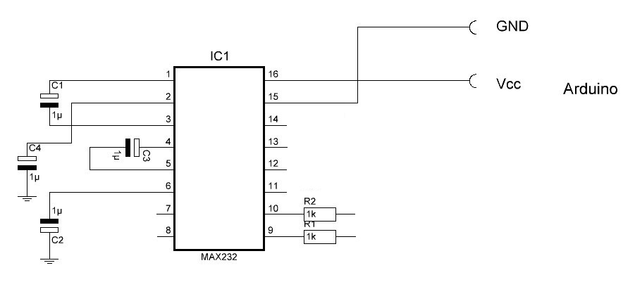
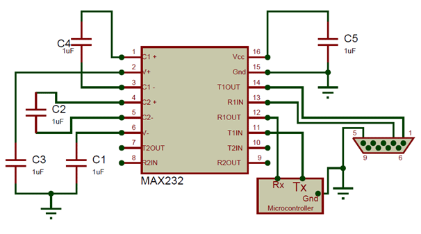
Figure 3: MAX board connection schematic. The MAX The IC work with the help of +5V, hence power the Vcc with +5V and the ground pin to circuit ground.
Every microcontroller that has Serial communication capability will have a Tx pin and a Rx pin. This is the TTL/CMOS logic inputs, and then the converter RS logic signals can be.
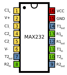
MAX dual transmitter / dual receiver RS chip in DIP package signal level conversion with an integrated circuit (IC) from the MAX family. MAX IC is used to convert the TTL/CMOS logic levels to RS logic levels during serial communication of MAX PinOut | IC MAXN pin diagram. With a MAX IC you can easily connect your PIC microcontroller to your PC.
to keep us on track and it gives us an overlook of what we want our circuit to do. When the block diagram is made, we’ll draw the schematic.Ttl To Rs Converter Circuit Diagram Schematics. All of these radio programming cables use a level converter circuit, RS to/from TTL.

The level converter can be as simple as two transistors,. One suggestion is that first you use RS to TTL signals.
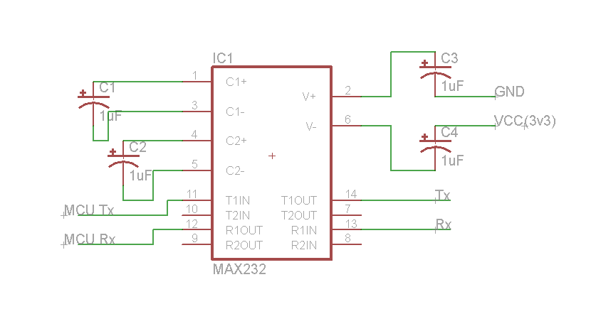
I made RS to RS converter using max and Max but in a mode that just receive data. New Kubota Ignition Switch Wiring Diagram – Encouraged for you to the website, in this particular occasion I’m going to show you regarding kubota ignition switch wiring diagramAnd now, this is actually the primary picture: power zd21 kubota starter wiring diagram ignition elegant for a from kubota ignition switch wiring diagram, source:schematron.org Jul 21, · RE: Circuit diagram of MAX and 89C51 Per Westermark Since you not only are missing the information how to connect the 89C51 to the MAX but also how to connect the MAX to a D-Sub connector, you most definitely haven’t spent a single minute looking for information yourself.
The MAX from Maxim was the first IC which in one package contains the necessary drivers (two) and receivers (also two), to adapt the RS signal voltage levels to TTL logic.
It became popular, because it just needs one voltage (+5V) and generates the necessary RS voltage levels (approx. .
Max ic circuit diagram together with sound sensor circuit diagram pdf in addition ultrasonic switch circuit in addition index2 further lm power supply furthermore an embedded system laboratory training using dspic30fa in addition final ppt also rs serial port pinout as well as dc dc converter 1 5 to 3v schematic also max further rs booster as well as rs to.Serial Programming/MAX Driver Receiver – Wikibooks, open books for an open worldSerial Programming/MAX Driver Receiver – Wikibooks, open books for an open world