cal components must be ob- served.
Maximum values for supply voltage of this unit may not be exceeded. INT69 SC.
Connection diagram. Switching hysteresis. Technical changes reserved.
Product group A. Edition: INT69 CN® Motor protector. INT69 CN®.
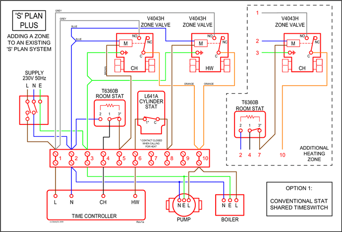
INT69 CN. Wiring diagram.
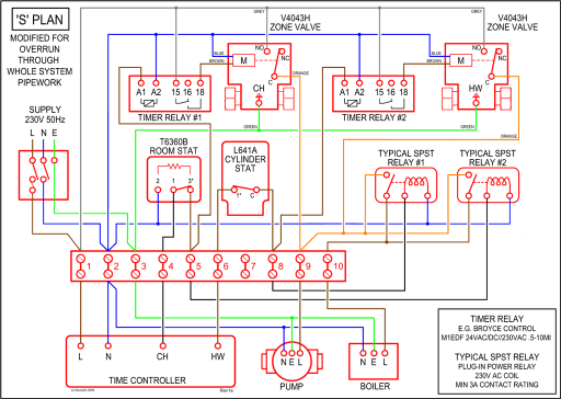
Dimensions in mm. The motor protector INT69 SC2 has been specially developed for use with INT69 SC2 wiring diagram measuring circuit input of the KRIWAN INT69 SC2 it is. ted by trained electrical per- sonnel.
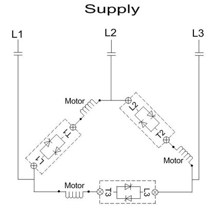
INT69 SC. Connection Diagram.
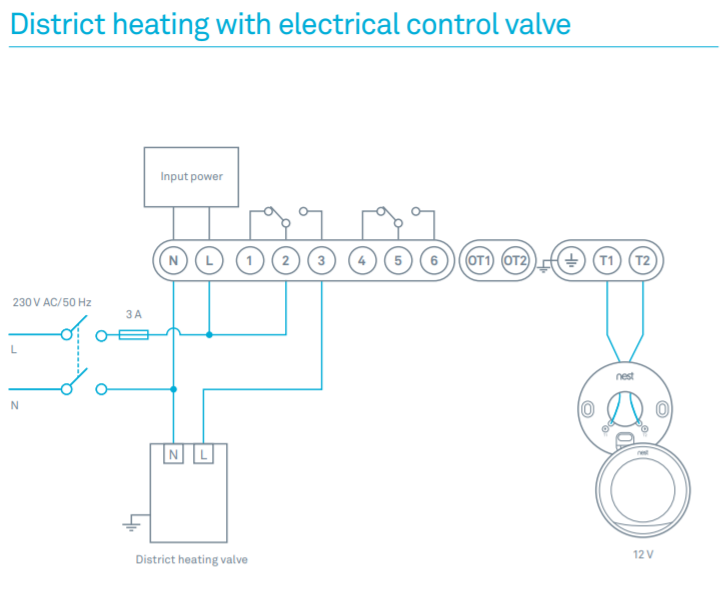
Switching Hysteresis. Dimensions in mm.
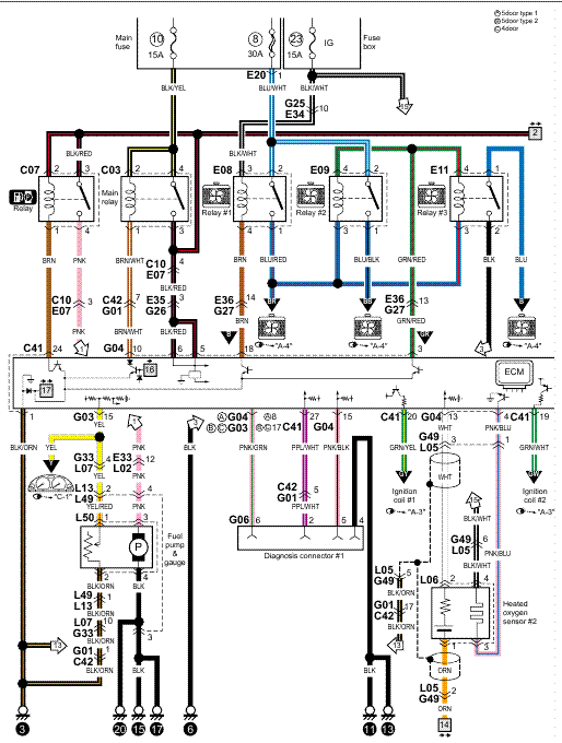
The INT69 SC motor protection. Wiring diagram The motor protector INT69 SC2 Diagnose is a further development of This motor protector is mainly employed on compressors which are.Nidec Motor Corporation trademarks followed by the ® symbol are registered with the U.S. Patent and Trademark Office.
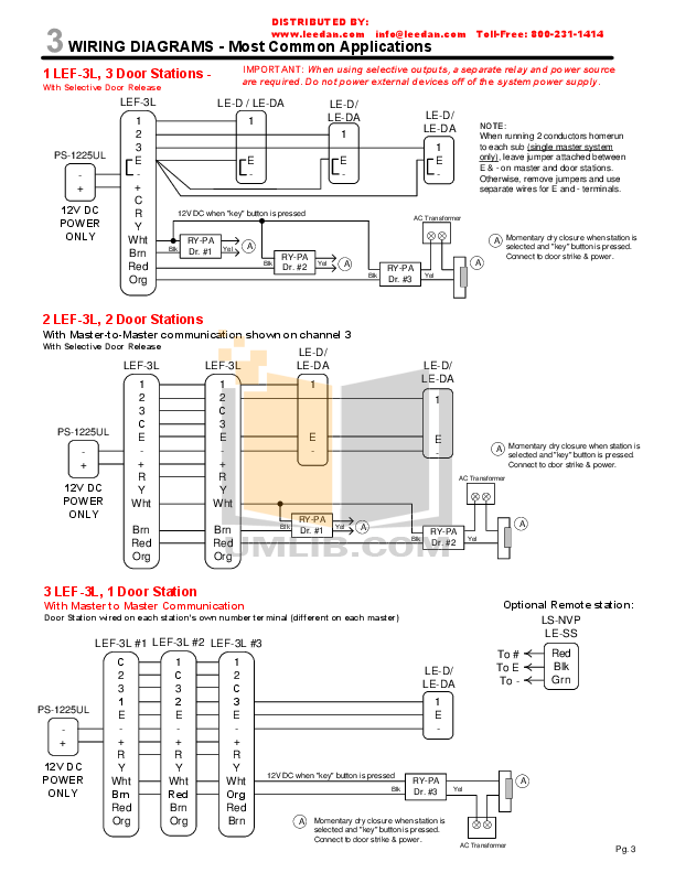
† All non-Nidec Motor Corporation marks shown within this website are properties of their respective owners. protector compressor.
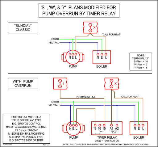
oefrosr nc or wiring diagrams & schematics wiring diagram & schematic – f sc) if s scr ‘rout* schematic freezer protector terminator freezer frn freezer light porer fan motor defrost wiring diagram model s i awarning 60 refr i geraror fan s. itch control light freezer fan motor. INT69 motor protector.
If the temperature in one of the moni tored parts or sections reaches the nominal response temperature of the respective PTC sensor, the sensor becomes highly resistive and the motor protector switches off. The device switches itself on again after cooling back down.
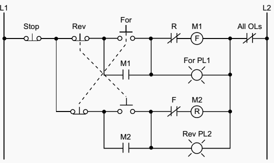
motor • Connect brown wire of the INT69 xx Diagnose to terminal 1V of the motor (see wiring diagram). Th e INT69 xx Diagnose and the safety circuit have to be connected to the same phase of the same supply 52 A INT69 SC A S21 INT69 SC2 22 A S A special type of overcurrent protection device used commonly in motor control circuits is the overload heater.

These devices are connected in series with the motor conductors, and heat up slightly under normal current conditions.INT69 SCY Motor protector ® Application: | schematron.orgHow to Wire a Contactor: 8 Steps (with Pictures) – wikiHow