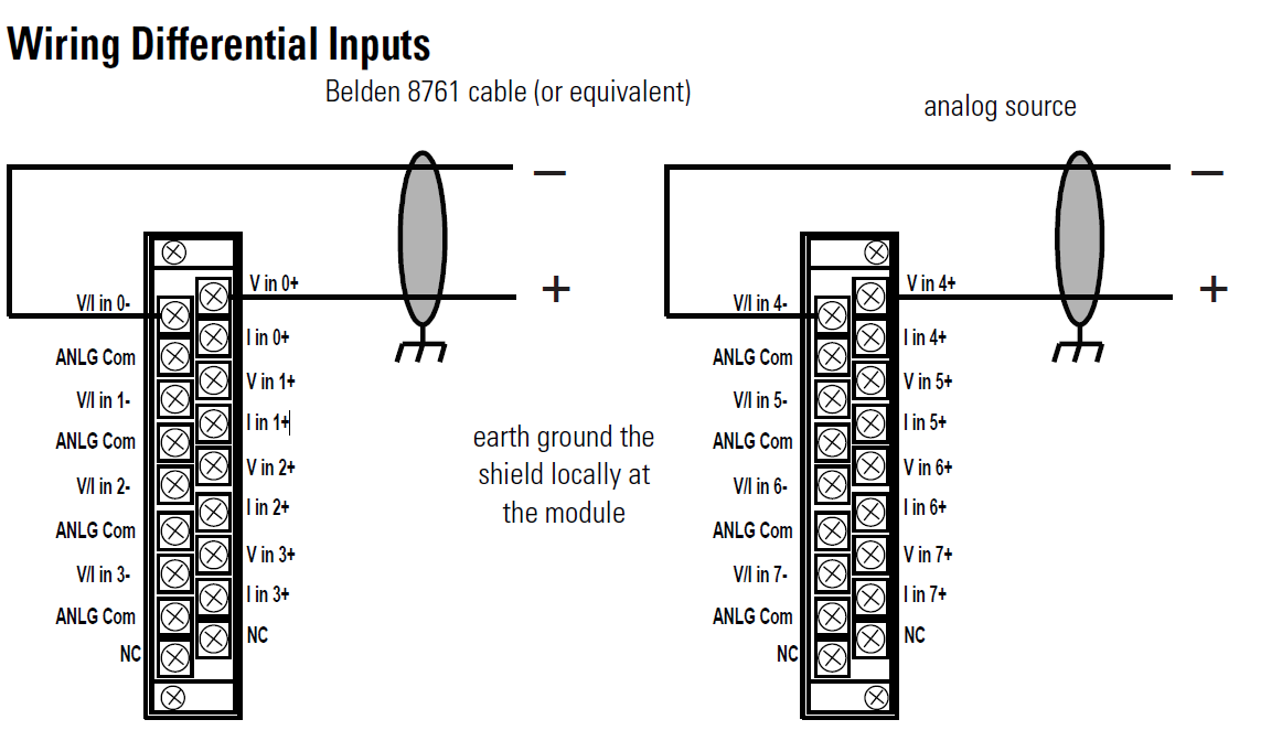
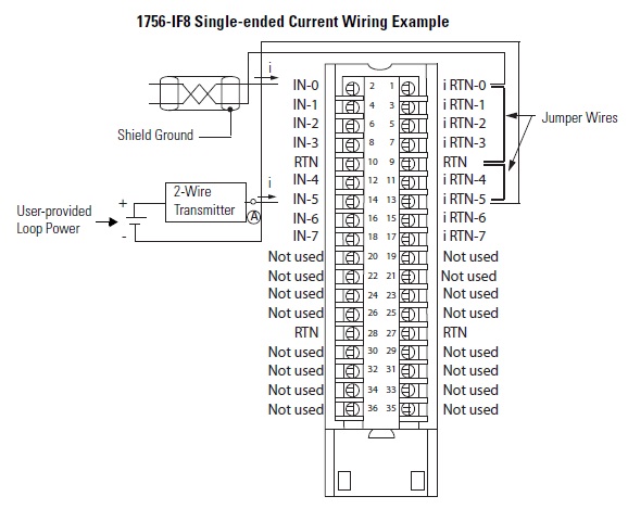
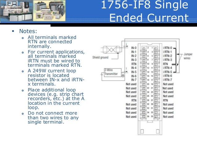
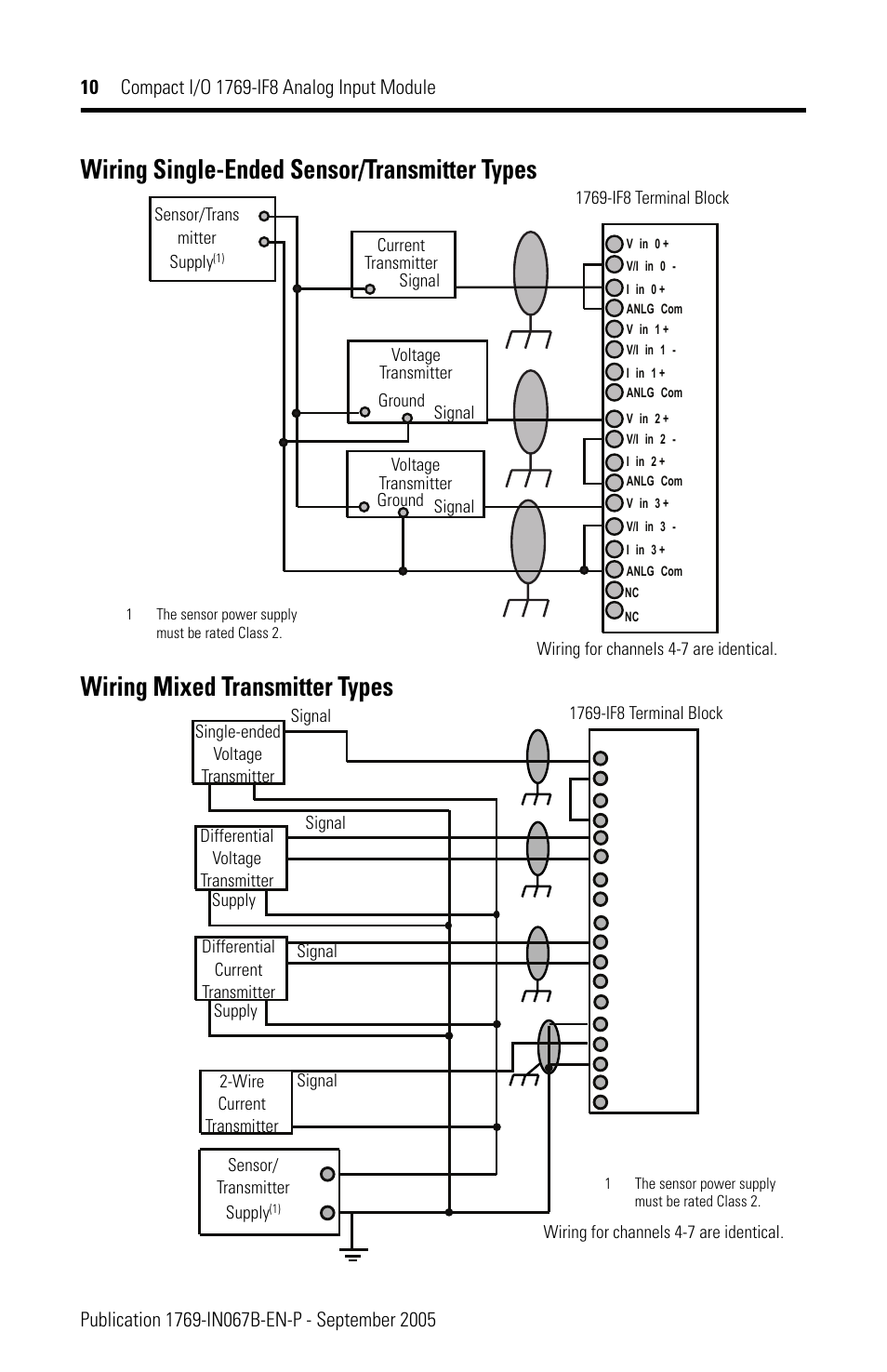
A-B IF8 ANALOG INPUT – CURRENT/VOLTAGE 8 PTS (36 PIN) Diagram , Single Ended Current (DWG) · Wiring Diagram, Single Ended Voltage (DWG). Differential analog inputs are more immune to noise than single-ended Supply.
IF8 Terminal Block. Sensor/.
Transmitter. Supply(1).
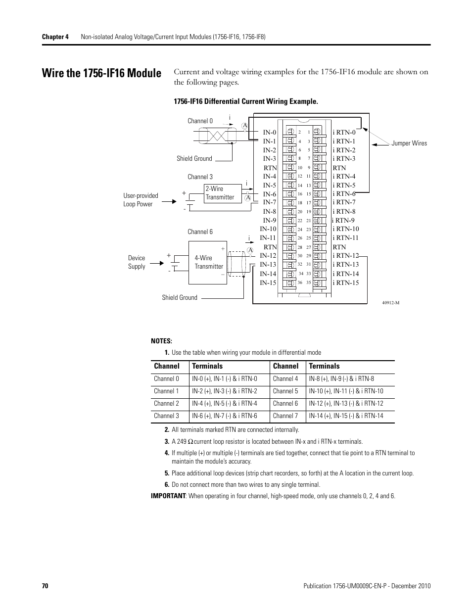
Wiring for channels. Find the Other Automation IF8 IF8 Allen Bradley at PDF Supply.
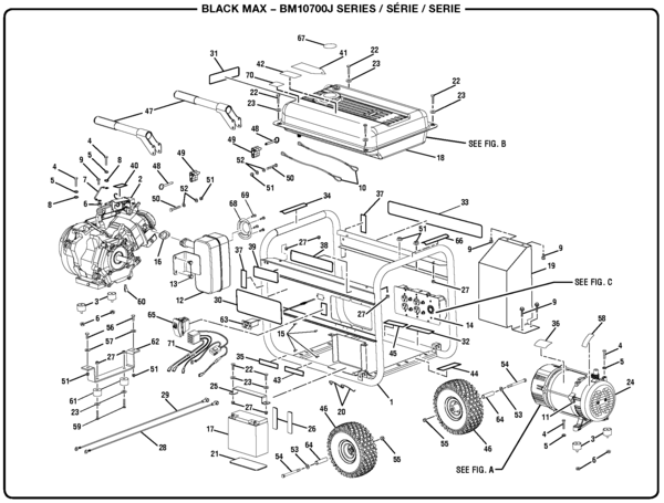
Download the technical manual for wiring and installation instructions. Single- ended wiring compares one side of the input signal to the ground signal and it is .
one end and free connectors ready to wire to I/O modules or other components on the .. Note: Bulletin module wiring diagrams are available at schematron.org com.
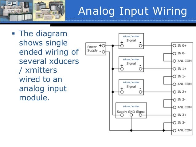
Refer to page IF8 Single-Ended Voltage. ACABLE➊TB. Do we have a wiring diagram showing how field devices are wired to a ControlLogix IF8 input card in Single Ended Current mode with AIFM8-FIF8, TC-IAH (Single-Ended Voltage) AIFM8-F-5 3-Wire Transmitter 4-Wire Transmitter +V +V 0F IN 0 +V OF IN 0 SHIELD Power Supply Transmitter IN-0 RTN RTN VCOM VCOM VCOM +V SHIELD Power Supply Transmitter IN-0 RTN RTN VCOM VCOM AIFM8-F-5 AIFM8-F-5 ACABLE TA HWACAB TA ACABLE TA HWACAB TA TC-IAH When using the single-ended wiring method, all input devices are tied to a common ground.
In addition to the common ground, the use of single-ended wiring maximizes the number of usable channels on the module (eight channels for the IF8 module and 16 channels for the IF16). Publication – November Summary of Changes Introduction This release of this document contains new information.
New Information Chapter 4 contains information on ControlLogix non-isolated analog input modules. Chapter 7 contains information on ControlLogix non-isolated analog.
1 Publication UMB-EN-P – June Preface About This User Manual What This Preface Contains This preface describes how to use this manual. The following table describes what this preface contains and its location.
Compact I/O Modules Specifications Each I/O module includes a built-in re movable terminal block with finger-safe cover for connections to I/O sensors and actuators. The terminal block is behind a door at the front of the module.
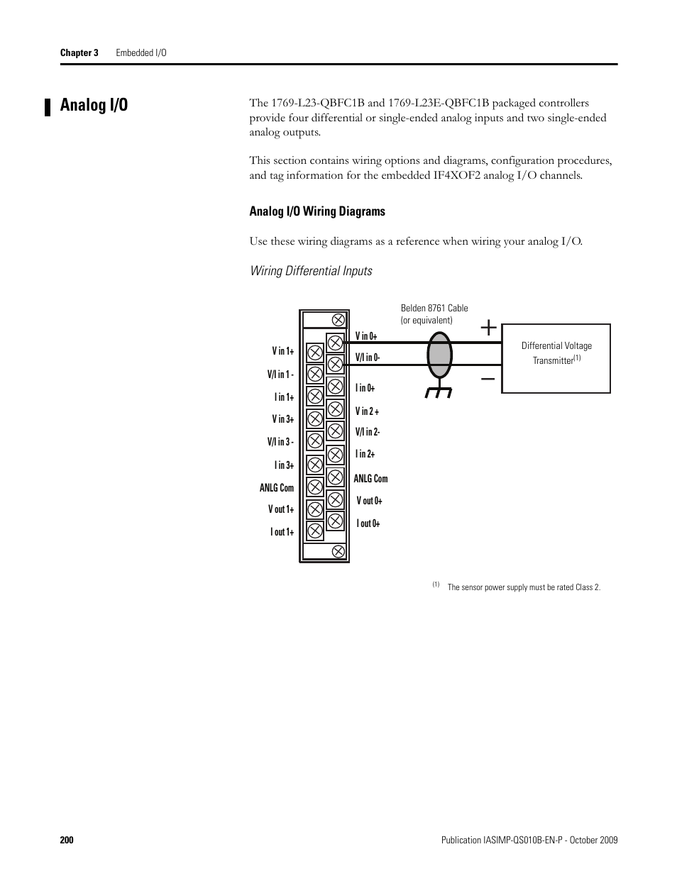
I/O wiring can be routed from beneath the module to the I/O terminals.Analog Input – Current/Voltage 8 Pts (36 Pin) || IF8IF8, 8 channels wiring diagram datasheet & applicatoin notes – Datasheet Archive